Railway, metro vehicles has wide use of CAN bus communication. Using its good real-time and error correction ability, improve the control efficiency and reliability of vehicle parts. But in metro operation, some lines will appear accidental CAN poor communications, node drop-off.
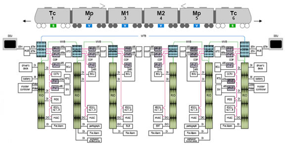
Field bus topology, as shown in figure 2, marshalling of metro vehicle for 6 section, where we test points in the air conditioning controller CAN interface position, the main test signal the CAN bus communication quality.
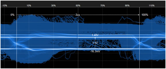
By eye diagram time measurement, the entire waveform doing eye diagram, measurement results visible waveform edge too slowly, a portion of the waveform is rising along with larger ringing, falling edge have bigger play phenomenon, that the bus has a discrete part of the signal. Difference level amplitude is less than the standard of 2.0 1.5 V V ISO11898-2 standard
1. The air conditioning of waveform analysis
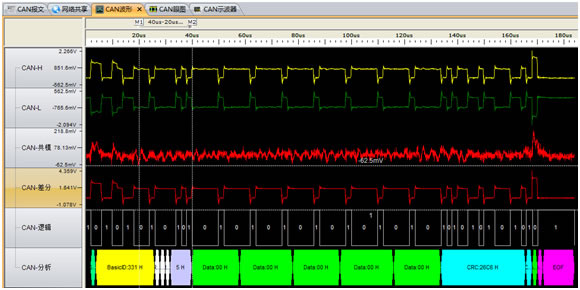
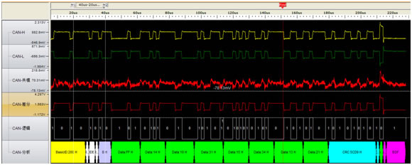
From air conditioning CAN frames with ID: 0 x331, x332 0, 0 x333, select one of the ID 0 x331 message, waveform as shown in figure 4. Visible difference level have obvious phenomenon of "play".
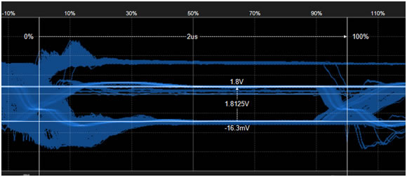
The ID 0 x331, 0 x332, 0 x333 frame waveform doing eye diagram, as shown in figure 5. CAN clearly see the CAN waveform amplitude is 1.5 V (those with high amplitude and other frame is raised when the arbitration).
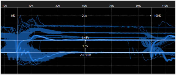
Steep analysis: CAN the differential waveform edge, the edge is clear, but the amplitude is 1.5 V, CAN than the standard difference level (at two ends of the euro 120 resistance) of 2.0 V to 0.5 V, the less there are two possible:
CANH on (1) the CAN interface and CANL may resistance of each series by about 10 euro 120 with two parallel partial pressure, to make the actual waveform is only 1.5 V. 1, with a power amplifier circuit, and through can make the control of its work;
(2) the network terminal resistance more added 1 euro 120, three 120 bus is what is the resistance, leading to reduced to 1.5 V voltage amplitude.
Look from the waveform, and obvious phenomenon of "play", air conditioning CAN interface position impedance discontinuity. , although its position is the actual terminal terminal resistance is not in it, or its position to the end of the long branches.
2. CAN master the waveform
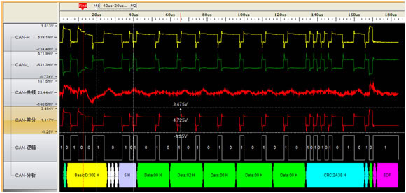
CAN master the CAN frame ID 0 x200, 0 x231. Select one of the ID 0 x200 message, waveform is shown in figure 6
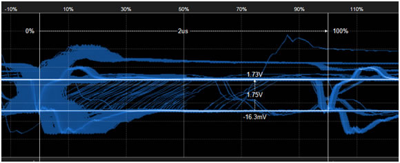
The ID 0 x200, 0 x231 frame waveform doing eye diagram, as shown in figure 7. CAN be clearly seen from the CAN from the master CAN wave reaches the air conditioning CAN interface of amplitude is 1.8 V (measurement point in the network card side, those with high amplitude and other frame is raised when the arbitration). Along with rising and falling waveform resides.
Analysis: the test points to measure the difference level of amplitude is 1.8 V, is less than the standard 2.0 V, 0.2 V, may be CAN master in CANH and CANL also series resistance, or the transmission wires, joint has certain pressure drop.
CAN increase along the slow suggests differential waveform from CAN master interface to the air conditioning CAN lead impedance is larger. Falling edge with corrugated reside, but also for its position is the actual terminal air conditioner CAN interface, but terminal resistance is not in it, or its position to the end of the long branches.
3. The actual connect resistor location of the node
The eye is done in the diagram as shown in figure 9.
Analysis: through the eye chart, its decline along a steep drop to zero, but then "bullet", explain the terminal resistance was installed above, but it is not the actual terminal, and from the actual terminal reflected wave, leading to "play".
From what has been discussed above
(1) of the system CAN wave exists serious phenomenon of "play", has lead to the risk of errors. Through the analysis of the front, is caused by the impedance discontinuity. Resistance and impedance discontinuity, is the bus terminal installation position error;
(2) the air conditioning CAN interface the resistance of the series is too big lead to partial pressure. Difference is only 1.5 V voltage amplitude, easy to changes in temperature, aging lines or voltage fluctuation, lead to an error or even communication can't do it. Please control series resistance not greater than 5.1 euro.
(3) transfer impedance conductor or joint is too large. Lead to rising slope too slowly, only 3.55 V/us, far less than 16 V/us standard value, easy to changes in temperature or long-term running, cause the failure of resynchronization of bit errors or mistakes, CRC check even unable to communication. Please check the transmission wire specifications, and joint resistance, ensure that the impedance is less than 0.02 euro/m (or the equivalent for the wire diameter of 1.0 was more shielded twisted-pair cable).