Sidebar
News Press

Administrator
Industrial RS485 to Fiber Optic Converter
RS-485 to Fiber Optic Converter
Point to point/Multi-drop Bus/Self-healing Ring Fiber Links
The RS-485/422 Fiber Optic Converter data series uses the most advanced digital technologies to provide excellent repeatable performance for today's data systems. It supports transmission of one bi-directional data channel over one multimode or singlemode optical fiber. RS232, RS422 and RS485 (2 wire & 4 wire) standards are fully supported. The plug-and-play design ensures ease of installation with no electrical or optical adjustment needed. LED indicators are provided to show the operational status of the unit clearly.
The series is available in compact wall mount or 3U chassis card.
The RS-485/422 Series converter is equipped with a multiple interface circuit that can handle RS-485/422 serial interfaces and multi-mode or single- mode fiber. RS-485/422 converters are used to extend serial transmission distance up to 2 km (multi-mode fiber) or up to 20-100km (single- mode fiber)...Auto Baud Rate DetectionThe RS-485/422 Series incorporates a method for automatically detecting the serial signal baud rate by hardware. This is an extremely convenient feature for the user. Even if a device's baud rate is changed, the signal will still be transmitted through the RS-485/422 to fiber converter without any problem.
Product Features
Supports RS232, RS422 and RS485
Multi mode and single mode solutions
Switchable 120Ω Termination and biasing
LED indicators provide quick diagnosis of all important system parameters
Up to 14 units in a 3U chassis
Compact and 3U chassis card configuration
Parameters:
| Data | |
| Data Formats | RS232,RS422,RS485 |
| RS232 Data Rate | 115.2kbps |
| RS422 / 485 Data Rate | 512 kbps or 1Mkbps |
| Bit Error Rate | <1 x 10-12 |
| Connectors | |
| Data | Screw Block Terminal |
| Fiber | ST, SC or FC (ST fitted as standard) |
| Environmental | |
| Operating Temperat ure | - 3 0 C--- +70 C |
| Storage Temperature | - 3 0 C--- +70 C |
| Operating Humidity | 0- 95% |
| MTBF | >100,000 Hours |
| Optical | |
| Fiber | Multi mode or Single mode |
| Wavelength | MM: 850/1310nm, SM: 1310/1550nm |
| Number of fibers | 2 or 1 |
| POWER | |
| Power Input | AC 220V 110v or DC+110V +5V +12V +24V +48V Option |
| Mechanical | |
| Dimensions | 125(L)×110(W)×36(H )Wall Mount & DIN Rail |
Ordering Information:
|
Model Number |
Description |
Fiber No. |
Fiber Mode |
Fiber Connector |
|
HFB-FO-485-P1M |
Point to point Link,Single Fiber(BI-DI), 2km |
1 |
Multi Mode |
ST/SC/FC |
|
HFB-FO-485-P2M |
Point to point Link,Dual Fiber, 2km |
2 |
Multi Mode |
ST/SC/FC |
|
HFB-FO-485-P1S |
Point to point Link,Single Fiber(BI-DI), 20km |
1 |
Single Mode |
ST/SC/FC |
|
HFB-FO-485-P2S |
Point to point Link,Dual Fiber, 20km |
2 |
Single Mode |
ST/SC/FC |
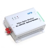
RS-232 Multi-Drop Self-Healing Ring Fiber Optic Converter(Wall Mount)
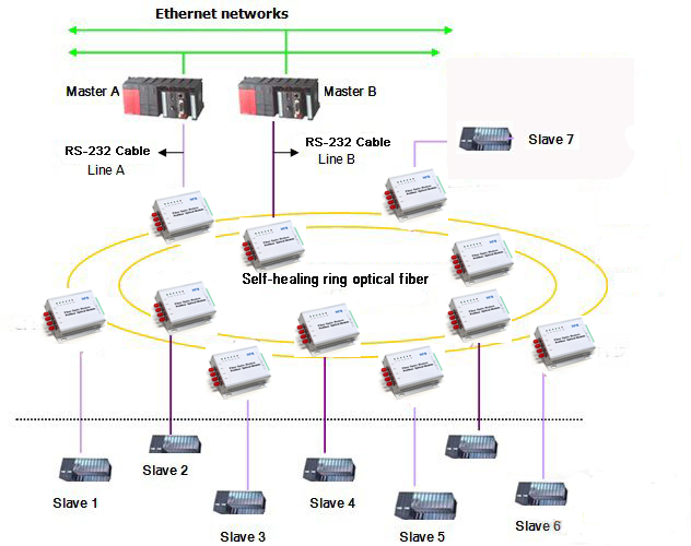
RS-232 Multi-Drop Self-Healing Ring Fiber Optic Converter
The Multi-Drop Self-Healing Ring Transmission series products provide an optical self-healing ring network for RS232, RS422 /RS485 data interfaces over two multimode or singlemode optical fibers. The system offers maximum reliability as it can recover simultaneous faults or failures in two different locations and has contact closure outputs on each module to clearly indicate any fault location. The self-healing ring consists of two opposing data paths, ring A and ring B. Under normal operation only the primary path (ring A) is used for data transfer. If a fault is detected, the data is transferred to the secondary path (ring B) without interruption to the communications network.
The series is available in wall mount, DIN rail or 3U chassis card.
Product Features
Supports RS232, RS422 and RS485
Multimode and singlemode solutions
Contact closure alarm outputs per station
Single or dual fibre configurations
Wall mount, DIN rail and 3U chassis card
Typical Topology:
Specification:
| Data | |
| Data Formats | RS232,RS422,RS485 |
| RS232 Data Rate | 115.2kbps |
| RS422 / 485 Data Rate | 512 kbps or 1Mkbps |
| Bit Error Rate | <1 x 10-12 |
| Connectors | |
| Data | Screw Block Terminal |
| Fiber | ST, SC or FC (ST fitted as standard) |
| Environmental | |
| Operating Temperat ure | - 3 0 C--- +70 C |
| Storage Temperature | - 3 0 C--- +70 C |
| Operating Humidity | 0- 95% |
| MTBF | >100,000 Hours |
| Optical | |
| Fiber | Multimode or singlemode |
| Wavelength | MM: 850nm, SM: 1310nmnm |
| Number of fibers | 4 or 2 |
| POWER | |
| Power Input | AC 220V 110v or DC+110V +5V +12V +24V +48V Option |
| Mechanical | |
| Dimensions | 125(L)×110(W)×36(H )Wall Mount & DIN Rail |
Ordering information:
|
Model Number |
Description |
Fiber No. |
Fiber Mode |
Fiber Connector |
|
HFB-FO-232-R2M |
Redundant Ring Link,Dual Fiber(BI-DI), 2km |
2 |
Multi Mode |
ST/SC/FC |
|
HFB-FO-232-R4M |
Redundant Ring Link,4 Fiber, 2km |
4 |
Multi Mode |
ST/SC/FC |
|
HFB-FO-232-R2S |
Redundant Ring,Dual Fiber(BI-DI), 20km |
2 |
Single Mode |
ST/SC/FC |
|
HFB-FO-232-R4S |
Redundant Ring,4 Fiber, 20km |
4 |
Single Mode |
ST/SC/FC |
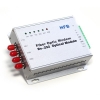
RS232 Multi-Drop Bus Fiber Optic Converter(Wall Mount)

RS232 Multi-Drop Bus Fiber Optic Converter
The RS- 232 Multi-Drop Bus Fiber Optic Modem series products provide an optical bus network for RS-232, RS-422 or RS-485 data interfaces over a pair of multimode or singlemode optical fibers. The Terminal module units operate as the end or terminal points and provide an electrical connection and a two fibre optical connection. The Repeater module units act as in-line repeater stations and provide a single electrical connection and two optical connections, one upstream and one downstream.
This series is available in either wall mount, DIN rail or 3U chassis card configurations.
Product Features
Multi protocol data interface
Switchable termination and biasing
Multimode and singlemode
Wall mount, DIN and 3U chassis card
Typical System Configuration
| Data | |
| Data Formats | RS232,RS422,RS485 |
| RS232 Data Rate | 115.2kbps |
| RS422 / 485 Data Rate | 512 kbps or 1Mkbps |
| Bit Error Rate | <1 x 10-12 |
| Connectors | |
| Data | Screw Block Terminal |
| Fiber | ST, SC or FC (ST fitted as standard) |
| Environmental | |
| Operating Temperat ure | - 3 0 C--- +70 C |
| Storage Temperature | - 40 C--- +85 C |
| Operating Humidity | 0- 95% |
| MTBF | >100,000 Hours |
| Optical | |
| Fiber | Multi mode or single mode |
| Wavelength | MM: 850nm, SM: 1310nm |
| Number of fibers | 4 or 2 |
| POWER | |
| Power Input | AC 220V 110v or DC+110V +5V +12V +24V +48V Option |
| Mechanical | |
| Dimensions | 125(L)×110(W)×36(H )Wall Mount & DIN Rail |
Ordering information:
|
Model Number |
Description |
Fiber No. |
Fiber Mode |
Fiber Connector |
|
HFB-FO-232-M2M |
Multi point Link,Dual Fiber(BI-DI), 2km |
2 |
Multi Mode |
ST/SC/FC |
|
HFB-FO-232-M4M |
Multi point Link,4 Fiber, 2km |
4 |
Multi Mode |
ST/SC/FC |
|
HFB-FO-232-M2S |
Multi point Link,Dual Fiber(BI-DI), 20km |
2 |
Single Mode |
ST/SC/FC |
|
HFB-FO-232-M4S |
Multi point Link,4 Fiber, 20km |
4 |
Single Mode |
ST/SC/FC |
Industrial RS232 to Fiber Optic Converter(Wall Mount)
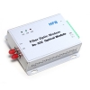
RS-232 Fiber Optic Converter
Point to point/Multi-drop Bus/Self-healing Ring
The HFB-FO-232 series uses the most advanced digital technologies to provide excellent repeatable performance for today's data systems. It supports transmission of one bi-directional data channel over one multimode or singlemode optical fiber. RS232, RS422 and RS485 standards are fully supported. The plug-and-play design ensures ease of installation with no electrical or optical adjustment needed. LED indicators are provided to show the operational status of the unit clearly.
The series is available in compact wall mount or 3U chassis card.
The RS-232 Series converter is equipped with a multiple interface circuit that can handle RS-232 serial interfaces and multi-mode or single- mode fiber. RS-232 converters are used to extend serial transmission distance up to 2 km (multi-mode fiber) or up to 20-100km (single- mode fiber)...Auto Baud Rate DetectionThe RS-232 Series incorporates a method for automatically detecting the serial signal baud rate by hardware. This is an extremely convenient feature for the user. Even if a device's baud rate is changed, the signal will still be transmitted through the RS-232 to fiber converter without any problem.
Product Features
Supports RS232, RS422 and RS485
Multimode and singlemode solutions
Switchable 120Ω Termination and biasing
LED indicators provide quick diagnosis of all important system parameters
Up to 14 units in a 3U chassis
Compact and 3U chassis card configuration
Typical System Configuration
| Data | |
| Data Formats | RS232,RS422,RS485 |
| RS232 Data Rate | 115.2kbps |
| RS422 / 485 Data Rate | 512 kbps or 1Mkbps |
| Bit Error Rate | <1 x 10-12 |
| Connectors | |
| Data | Screw Block Terminal |
| Fiber | ST, SC or FC (ST fitted as standard) |
| Environmental | |
| Operating Temperat ure | - 3 0 C--- +70 C |
| Storage Temperature | - 40 C--- +85 C |
| Operating Humidity | 0- 95% |
| MTBF | >100,000 Hours |
| Optical | |
| Fiber | Multimode or singlemode |
| Wavelength | MM: 850nm, SM: 1310nm |
| Number of fibers | 4 or 2 |
| POWER | |
| Power Input | AC 220V 110v or DC+110V , +5V , +12V , +24V , +48V Option |
| Mechanical | |
| Dimensions | 125(L)×110(W)×36(H )Wall Mount & DIN Rail |
Ordering information:
|
Model Number |
Description |
Fiber No. |
Fiber Mode |
Fiber Connector |
|
HFB-FO-232-P1M |
Point to point Link,Single Fiber(BI-DI), 2km |
1 |
Multi Mode |
ST/SC/FC |
|
HFB-FO-232-P2M |
Point to point Link,Dual Fiber, 2km |
2 |
Multi Mode |
ST/SC/FC |
|
HFB-FO-232-P1S |
Point to point Link,Single Fiber(BI-DI), 20km |
1 |
Single Mode |
ST/SC/FC |
|
HFB-FO-232-P2S |
Point to point Link,Dual Fiber, 20km |
2 |
Single Mode |
ST/SC/FC |
Profibus Multi-Drop Bus Fiber Optic Converter(Wall Mount)

Profibus Multi-Drop Bus Fiber Optic Converter
Product Description
The Profibus Multi-Drop Bus Fiber Optic Modem series products provide an optical bus network for Profibus, data interfaces over a pair of multimode or singlemode optical fibers. The Terminal module units operate as the end or terminal points and provide an electrical connection and a two fibre optical connection. The Repeater module units act as in-line repeater stations and provide a single electrical connection and two optical connections, one upstream and one downstream.
This series is available in either wall mount, DIN rail or 3U chassis card configurations.
Product Features
Up to 1.5Mbps data rate
Multimode and singlemode
Single fiber solution
Wall mount, rack or chassis configurations
| Data | |
| Data Formats | Siemens Profibus RS-485 |
| Profibus Data Rate | 0~1.5Mbps/3Mbps/6Mbps/12Mbps for Options |
| Bit Error Rate | <1 x 10-12 |
| Connectors | |
| Data | Screw Block Terminal |
| Fiber | ST, SC or FC (ST fitted as standard) |
| Environmental | |
| Operating Temperat ure | - 3 0 C--- +70 C |
| Storage Temperature | - 40 C--- +85 C |
| Operating Humidity | 0- 95% |
| MTBF | >100,000 Hours |
| Optical | |
| Fiber | Multimode or Singlemode |
| Wavelength | MM: 850, SM: 1310nm |
| Number of fibers | 4 or 2 |
| POWER | |
| Power Input | AC 220V 110v or DC+110V +5V +12V +24V +48V Option |
| Mechanical | |
| Dimensions | 125(L)×110(W)×36(H )Wall Mount & DIN Rail |
Ordering Information:
|
Model Number |
Description |
Fiber No. |
Fiber Mode |
Fiber Connector |
|
HFB-FO-PRO-M2M |
Multi point Link,Dual Fiber(BI-DI), 2km |
2 |
Multi Mode |
ST/SC/FC |
|
HFB-FO-PRO-M4M |
Multi point Link,4 Fiber, 2km |
4 |
Multi Mode |
ST/SC/FC |
|
HFB-FO-PRO-M2S |
Multi point Link,Dual Fiber(BI-DI), 20km |
2 |
Single Mode |
ST/SC/FC |
|
HFB-FO-PRO-M4S |
Multi point Link,4 Fiber, 20km |
4 |
Single Mode |
ST/SC/FC |
Profibus Multi-Drop Self-Healing Ring Fiber Optic Modem(Wall Mount)

Profibus Self-Healing Ring Fiber Optic Converter
Product Description
Profibus Multi-Drop Self-Healing Ring Fiber Optic Modem One Channel Multi Protocol Bi-Directional Data
The Multi-Drop Self-Healing Ring Transmission series products provide an optical self-healing ring network for Profibus data interfaces over two multimode or singlemode optical fibers. The system offers maximum reliability as it can recover simultaneous faults or failures in two different locations and has contact closure outputs on each module to clearly indicate any fault location. The self-healing ring consists of two opposing data paths, ring A and ring B. Under normal operation only the primary path (ring A) is used for data transfer. If a fault is detected, the data is transferred to the secondary path (ring B) without interruption to the communications network.
The series is available in wall mount, DIN rail or 3U chassis card.
Product Features
- Multimode and singlemode solutions
- Contact closure alarm outputs per station
- Single or dual fibre configurations
- Wall mount, DIN rail and 3U chassis card
Specification
| Data | |
| Data Formats | Siemens Profibus RS-485 |
| Profibus Data Rate | 0~1.5Mbps/3Mbps/6Mbps/12Mbps for Options |
| Bit Error Rate | <1 x 10-12 |
| Connectors | |
| Data | Screw Block Terminal |
| Fiber | ST, SC or FC (ST fitted as standard) |
| Environmental | |
| Operating Temperat ure | - 3 0 C--- +70 C |
| Storage Temperature | -40 C--- +85 C |
| Operating Humidity | 0- 95% |
| MTBF | >100,000 Hours |
| Optical | |
| Fiber | Multi mode or Single mode |
| Wavelength | MM: 850nm, SM: 1310nm |
| Number of fibers | 4 or 2 |
| POWER | |
| Power Input | AC 220V 110v or DC+110V +5V +12V +24V +48V Option |
| Mechanical | |
| Dimensions | 125(L)×110(W)×36(H )Wall Mount & DIN Rail |
Ordering Information:
|
Model Number |
Description |
Fiber No. |
Fiber Mode |
Fiber Connector |
|
HFB-FO-PRO-R2M |
Redundant Ring Link,Dual Fiber(BI-DI), 2km |
2 |
Multi Mode |
ST/SC/FC |
|
HFB-FO-PRO-R4M |
Redundant Ring Link,4 Fiber, 2km |
4 |
Multi Mode |
ST/SC/FC |
|
HFB-FO-PRO-R2S |
Redundant Ring,Dual Fiber(BI-DI), 20km |
2 |
Single Mode |
ST/SC/FC |
|
HFB-FO-PRO-R4S |
Redundant Ring,4 Fiber, 20km |
4 |
Single Mode |
ST/SC/FC |
Profibus to Fiber Optic Converter(Wall Mount)
Profibus to Fiber Optic Converter
Profibus OLM (G11/12) Point to Point / Multi-drop Bus / Self-healing Ring
Product Description
The HFB-FO-PRO data series uses the most advanced digital technologies to provide excellent repeatable performance for today's data systems. It supports transmission of one bi-directional data channel over one multimode or singlemode optical fiber. Profibus standards are fully supported. The plug-and-play design ensures ease of installation with no electrical or optical adjustment needed. LED indicators are provided to show the operational status of the unit clearly.
The series is available in compact wall mount or 3U chassis card.
The profibus Series converter is equipped with a multiple interface circuit that can handle profibus serial interfaces and multi-mode or single- mode fiber. Profibus converters are used to extend serial transmission distance up to 2 km (multi-mode fiber) or up to 20-100km (single- mode fiber)...Auto Baud Rate DetectionThe profibus Series incorporates a method for automatically detecting the serial signal baud rate by hardware. This is an extremely convenient feature for the user. Even if a device's baud rate is changed, the signal will still be transmitted through the Profibus to fiber converter without any problem.
Product Features
- Up to 1.5 to 12Mbps data rate
- Multimode and singlemode
- Single fiber solution
- Wall mount, rack or chassis configurations
| Data | |
| Data Formats | Siemens Profibus RS-485 |
| Profibus Data Rate | 0~1.5Mbps/3Mbps/6Mbps/12Mbps for Options |
| Bit Error Rate | <1 x 10-12 |
| Connectors | |
| Data | Screw Block Terminal |
| Fiber | ST, SC or FC (ST fitted as standard) |
| Environmental | |
| Operating Temperat ure | - 3 0 C--- +70 C |
| Storage Temperature | - 40 C--- +85C |
| Operating Humidity | 0- 95% |
| MTBF | >100,000 Hours |
| Optical | |
| Fiber | Multi mode or Single mode |
| Wavelength | MM: 850, SM: 1310nm |
| Number of fibers | 2 or 1 |
| POWER | |
| Power Input | AC 220V 110v or DC+110V +5V +12V +24V +48V Option |
| Mechanical | |
| Dimensions | 125(L)×110(W)×36(H )Wall Mount & DIN Rail |
Ordering Information:
|
Model Number |
Description |
Fiber No. |
Fiber Mode |
Fiber Connector |
|
HFB-FO-PRO-P1M |
Point to Point Link,Single Fiber(BI-DI), 2km |
1 |
Multi Mode |
ST/SC/FC |
|
HFB-FO-PRO-P2M |
Point to Point Link,Dual Fiber, 2km |
2 |
Multi Mode |
ST/SC/FC |
|
HFB-FO-PRO-P1S |
Point to Point Link,Single Fiber(BI-DI), 20km |
1 |
Single Mode |
ST/SC/FC |
|
HFB-FO-PRO-P2S |
Point to Point Link,Dual Fiber, 20km |
2 |
Single Mode |
ST/SC/FC |
|
|
|
|
|
|
|
HFB-FO-PRO-M2M |
Multi Point Link,Dual Fiber(BI-DI), 2km |
2 |
Multi Mode |
ST/SC/FC |
|
HFB-FO-PRO-M4M |
Multi Point Link,4 Fiber, 2km |
4 |
Multi Mode |
ST/SC/FC |
|
HFB-FO-PRO-M2S |
Multi Point Link,Dual Fiber(BI-DI), 20km |
2 |
Single Mode |
ST/SC/FC |
|
HFB-FO-PRO-M4S |
Multi Point Link,4 Fiber, 20km |
4 |
Single Mode |
ST/SC/FC |
|
|
|
|
|
|
|
HFB-FO-PRO-R2M |
Redundant Ring Link,Dual Fiber(BI-DI), 2km |
2 |
Multi Mode |
ST/SC/FC |
|
HFB-FO-PRO-R4M |
Redundant Ring Link,4 Fiber, 2km |
4 |
Multi Mode |
ST/SC/FC |
|
HFB-FO-PRO-R2S |
Redundant Ring,Dual Fiber(BI-DI), 20km |
2 |
Single Mode |
ST/SC/FC |
|
HFB-FO-PRO-R4S |
Redundant Ring,4 Fiber, 20km |
4 |
Single Mode |
ST/SC/FC |
Contact Us
BuenoElectric China
Contact E-mails:
For purchase inquiry: This email address is being protected from spambots. You need JavaScript enabled to view it.
BuenoElectric USA
Tel: +1-724-994-0923
Fax: +1-813-990 3940
What Makes a Good PLC Program?
PLC programmers have been faced with a steep learning curve over the last 25 years, as technologies have moved quickly and almost all industries have implemented programmable logic controllers as a standard. This means that good experienced programmers are hard to find, and while most companies offer programming services there are important features which are often missed out.
Firstly a PLC programmer should write code so that it can be easily understood. Documentation and structure are essential. This often involves a working knowledge of the plant or process, a good PLC should be able to solve engineering problems from a specification, not just produce lines of code. From my experience the best PLC programmers are always firstly engineers.
Secondly the end user should never need to look at the PLC programmer's code this might seem a contradiction of point one but a good program will perform without intervention. I work on the theory if something looks rushed and untidy it usually is.
Thirdly think robustness this means if a machine or process stops the operator/technician should know why straight away, diagnosing software faults should not require a specialist. With the implementation of field busses and integrated devices this becomes increasingly difficult as programmers often adopt the Idea of it works leave it, upon the first failure nobody can ever diagnose the issue. When using new technologies time should be spent looking at the functionality. In a recent project I managed to mimic the entire Profibus network with over 50 drives into the SCADA, two days later a drive faulted and an operator was able to show the maintenance guy exactly where the fault was, the drive was replaced and production resumed within half an hour. Think information and look at what can hang up the operation.
One good technique I have found on making code more robust is sequential counts; I have spent the last 5 years developing my own ladder sequential charts. After working with manufacturers own add -on packages ,at a premium, my opinion is ladder steps are more cost effective and usable.
Documentation - As a minimum every PLC code should include as a minimum an Operand comment, whether this is an input output or internal register. In my project I will also always try to cross reference this with the electrical drawing. Block Comment the first block in a PLC code should include important traceability information, a comment of any modifications the date and reasons should be quickly visible. Rung comment all rungs should give a functional description of what they are doing.
Structure - Structure should always follow the flow of the machine, for example a packaging machine should start a infeed, define each operation in a separate routine and end with the out feed. This technique seems to have been missed by many programmers making diagnosis and modification difficult.
It should never be underestimated how much machine/process availability can be increased through good programming techniques. Remember PLC programming is not a black art, just because something is not visible does not mean it should not be done correctly. Always demand more from systems integrators and PLC programmers.
Brief Overview of Network Transceivers
Are you planning to install a network transceiver for the internet connection in your system? Do you have the basic knowledge on how the network transceivers work? Here's is a brief discussion on network transceivers which will guide you about its basic functionalities.
The term network is the modified name for transmitter-receiver, which are essentially the devices used for transmitting and receiving the analog and digital signals. Network transceivers are also used as the term, which is common for local-area network (LAN) connection and significantly detects digital signals coming to the network wire as well as transmitting the signals through the same network wire. In most of the modern LANs, the network transceivers are integrated into the network interface card (NIC), whereas, in many other networks, they function as external transmitter-receiver. Therefore, you need to check out what kind of transceivers will function for your network, and based on the criteria, you need to buy appropriate transceivers. In plain terms, a transmitter-receiver is an electronic device and this electronic device plays takes charge of global communication. The efficiency of transmitter -receiver depends on the how compatible it is over the network. Transceivers are known by other names also. For example, in case of Ether networks, transceiver is known for the Medium Access Unit (MAU). Likewise, in case of the radio communications, transmitter-receiver functions as a two way radio where a compatible combination occurs in the form or radio, transmitter and the receiver. Inside a radio unit, the transmitter -receiver exchanges information in half-duplex mode.
Network transceivers come in three configurations, namely chip, board, or module style. The size as well as the process of installation of all three transmitter-receivers is quite different. Chip style network transceiver is the smallest in size and a classic example of nano technology. Chip style network transceiver can be easily installed and removed from the network. Since these types of network are small in size, they are also very easy to handle. Board style transceivers are built or rather integrated directly into a network board or card. These types of transmitter-receiver form the part of motherboard and cannot be easily removed like the Chip style network. Module network transmitter-receivers are exclusively designed to work in the external networks and their installation and function is similar to the many other computer peripheral devices. There are many other designs of module type transmitter-receivers which ideally function as the stand-alone devices.
Transceivers are uniquely designed, and as the result of their uniqueness, they function within the circumference of specifically designed network protocols. The most common and advanced network protocols include AppleTalk®, CANbus, ControlNet, DeviceNet, Ethernet, Fibre Channel, FDDI, Fieldbus, Frame Relay, INTERBUS, PROFIBUS, and xDSL. It is important to know here that when you install the network on to the digital system, you should be aware about its compatibility with the other hardware characteristics. These network protocols are compatible with a particular genre of transmitter-receiver. Some of the quick run through specifications which you need to consider when buying transceivers includes compatibility with the peripherals, do they come with or without full duplex capabilities, different types of connection ports and many more. The full duplex ability of transceivers allows the transmission of data simultaneously to and fro in the network wire