Sidebar
News Press

Administrator
The Introduction and Application of PLC
The introduction and application of PLC
1.Motivation
Programmable Logic Controllers (PLC), a computing device invented by Richard E. Morley in 1968, have been widely used in industry including manufacturing systems, transportation systems, chemical process facilities, and many others. At that time, the PLC replaced the hardwired logic with soft-wired logic or so-called relay ladder logic (RLL), a programming language visually resembling the hardwired logic, and reduced thereby the configuration time from 6 months down to 6 days [Moody and Morley, 1999].
Although PC based control has started to come into place, PLC based control will remain the technique to which the majority of industrial applications will adhere due to its higher performance, lower price, and superior reliability in harsh environments. Moreover, according to a study on the PLC market of Frost and Sullivan [1995], an increase of the annual sales volume to 15 million PLCs per year with the hardware value of more than 8 billion US dollars has been predicted, though the prices of computing hardware is steadily dropping. The inventor of the PLC, Richard E Morley, fairly considers the PLC market as a 5-billion industry at the present time.
Though PLCs are widely used in industrial practice, the programming of PLC based control systems is still very much relying on trial-and-error. Alike software engineering, PLC software design is facing the software dilemma or crisis in a similar way. Morley himself emphasized this aspect most forcefully by indicating [Moody and Morley, 1999, p. 110]:
`If houses were built like software projects, a single woodpecker could destroy civilization.”
Particularly, practical problems in PLC programming are to eliminate software bugs and to reduce the maintenance costs of old ladder logic programs. Though the hardware costs of PLCs are dropping continuously, reducing the scan time of the ladder logic is still an issue in industry so that low-cost PLCs can be used.
In general, the productivity in generating PLC is far behind compared to other domains, for instance, VLSI design, where efficient computer aided design tools are in practice. Existent software engineering methodologies are not necessarily applicable to the PLC based software design because PLC-programming requires a simultaneous consideration of hardware and software. The software design becomes, thereby, more and more the major cost driver. In many industrial design projects, more than SO0/a of the manpower allocated for the control system design and installation is scheduled for testing and debugging PLC programs [Rockwell, 1999].
In addition, current PLC based control systems are not properly designed
to support the growing demand for flexibility and reconfigurability of manufacturing systems. A further problem, impelling the need for a systematic design methodology, is the increasing software complexity in large-scale projects.
2.The Introduction of PLC
A PLC (i.e. Programmable Logic Controller) is a device that was invented to replace the necessary sequential relay circuits for machine control. The PLC works by looking at its inputs and depending upon their state, turning on/off its outputs. The user enters a program, usually via software, that gives the desired results.
PLCs are used in many "real world" applications. If there is industry present, chances are good that there is a plc present. If you are involved in machining, packaging, material handling, automated assembly or countless other industries you are probably already using them. If you are not, you are wasting money and time. Almost any application that needs some type of electrical control has a need for a plc.
For example, let's assume that when a switch turns on we want to turn a solenoid on for 5 seconds and then turn it off regardless of how long the switch is on for. We can do this with a simple external timer. But what if the process included 10 switches and solenoids? We would need 10 external timers. What if the process also needed to count how many times the switches individually turned on? We need a lot of external counters.
As you can see the bigger the process the more of a need we have for a PLC. We can simply program the PLC to count its inputs and turn the solenoids on for the specified time.
This site gives you enough information to be able to write programs far more complicated than the simple one above. We will take a look at what is considered to be the "top 20" plc instructions. It can be safely estimated that with a firm understanding of these instructions one can solve more than 80% of the applications in existence.
In the late 1960's PLCs were first introduced. The primary reason for designing such a device was eliminating the large cost involved in replacing the complicated relay based machine control systems. Bedford Associates (Bedford, MA) proposed something called a Modular Digital Controller (MODICON) to a major US car manufacturer. Other companies at the time proposed computer based schemes, one of which was based upon the PDP-8. The MODICON 084 brought the world's first PLC into commercial production.
When production requirements changed so did the control system. This becomes very expensive when the change is frequent. Since relays are mechanical devices they also have a limited lifetime which required strict adhesion to maintenance schedules. Troubleshooting was also quite tedious when so many relays are involved. Now picture a machine control panel that included many, possibly hundreds or thousands, of individual relays. The size could be mind boggling. How about the complicated initial wiring of so many individual devices! These relays would be individually wired together in a manner that would yield the desired outcome. Were there problems? You bet!
These "new controllers" also had to be easily programmed by maintenance and plant engineers. The lifetime had to be long and programming changes easily performed. They also had to survive the harsh industrial environment. That's a lot to ask! The answers were to use a programming technique most people were already familiar with and replace mechanical parts with solid-state ones.
In the mid70's the dominant PLC technologies were sequencer state-machines and the bit-slice based CPU. The AMD 2901 and 2903 were quite popular in Modicon and A-B PLCs. Conventional microprocessors lacked the power to quickly solve PLC logic in all but the smallest PLCs. As conventional microprocessors evolved, larger and larger PLCs were being based upon them. However, even today some are still based upon the 2903(ref A-B's PLC-3) Modicon has yet to build a faster PLC than their 984A/B/X which was based upon the 2901.
Communications abilities began to appear in approximately 1973. The first such system was Modicon's Modbus. The PLC could now talk to other PLCs and they could be far away from the actual machine they were controlling. They could also now be used to send and receive varying voltages to allow them to enter the analog world. Unfortunately, the lack of standardization coupled with continually changing technology has made PLC communications a nightmare of incompatible protocols and physical networks. Still, it was a great decade for the PLC!
The 80's saw an attempt to standardize communications with General Motor's manufacturing automation protocol(MAP). It was also a time for reducing the size of the PLC and making them software programmable through symbolic programming on personal computers instead of dedicated programming terminals or handheld programmers. Today the world's smallest PLC is about the size of a single control relay!
The 90's have seen a gradual reduction in the introduction of new protocols, and the modernization of the physical layers of some of the more popular protocols that survived the 1980's. The latest standard (IEC 1131-3) has tried to merge plc programming languages under one international standard. We now have PLCs that are programmable in function block diagrams, instruction lists, C and structured text all at the same time! PC's are also being used to replace PLCs in some applications. The original company who commissioned the MODICON 084 has actually switched to a PC based control system.
3.PLC characteristic
The PLC characteristic reliability is high and the anti-interference ability is strong
High reliability is an electricity control system key function.Adopt strict productive technology fabrication since PLC adopt the modern large-scale integrated circuit technology,the inside circuit has adopted the anti-interference advanced technology , so it has very high reliability.For example,The F series PLC average nothing malfunction time that the Mitsubishi company produces is up to 300,000 hours.And hat some use average fault-free redundancy CPU PLC on-time is longer.The machine from PLC to inspect with outside circuit , use PLC to compose navar, electricity contactor system is compared with equal scale succeeding , electricity connection and switch contact already have fallen off to counting hundred counting a thousandth even , the malfunction reduces also right away greatly.Besides, PLC checks a function, when the malfunction appears but issues alarm information in time with hardware malfunction ego.Also,Applying person to application software can be compiled into outer-ring component malfunction from diagnose procedure , makes to gain certainly diagnose protection of malfunction also in system except circuit and equipment outside PLC.Such , entire system have had extremely high reliability being unable to accommodate oneself to queer.
1) The function is perfect , serviceability is strong
PLC develops the product having already formed big , small and medium, various scale seriation to today.Can be used for various scale industrial control occasion.Except logic treatment function, modern PLC has the perfect data arithmetic ability mostly , may be used for various digital control field.The PLC function element springs up in recent years in large amount , has made PLC penetration arrive at various industrial control such as location under the control of , the temperature under the control of , CNC.
2) Engineers and technicians easy to learn easy to use
PLC is the industrial control computer being applied or used universally , the labor being to be geared to the needs of factories , mines and enterprises charges equipment.Its interface is easy , the programming language accepts easily for engineers and technicians.
3) Systematic design and formation amount of work are small ,easy to reform and upkeep
PLC uses memory logic to replace the logic working a telephone switchboard , having decreased by external connection of control system greatly, makes control system design and the period being constuct with shorten extremely , the upkeep also becomes easy to get up at the same time.More important being makes with a equipment to become possibility process altering the procedure changing procedure of production.This very much be suitable to many breeds , minor the batches childbirth occasion.
4) Small Volume 、light weight、 low energy consumption
Take subminiature PLC as example, the breed bottom dimension producing is smaller than 100 mms , weight is smaller than 150 gs , the power dissipation counts a tile only.
4.Objective and Significance of the Thesis
The objective of this thesis is to develop a systematic software design methodology for PLC operated automation systems. The design methodology involves high-level description based on state transition models that treat automation control systems as discrete event systems, a stepwise design process, and set of design rules providing guidance and measurements to achieve a successful design. The tangible outcome of this research is to find a way to reduce the uncertainty in managing the control software development process, that is, reducing programming and debugging time and their variation, increasing flexibility of the automation systems, and enabling software reusability through modularity. The goal is to overcome shortcomings of current programming strategies that are based on the experience of the individual software developer.
A systematic approach to designing PLC software can overcome deficiencies in the traditional way of programming manufacturing control systems, and can have wide ramifications in several industrial applications. Automation control systems are modeled by formal languages or, equivalently, by state machines. Formal representations provide a high-level description of the behavior of the system to be controlled. State machines can be analytically evaluated as to whether or not they meet the desired goals. Secondly, a state machine description provides a structured representation to convey the logical requirements and constraints such as detailed safety rules. Thirdly, well-defined control systems design outcomes are conducive to automatic code generation- An ability to produce control software executable on commercial distinct logic controllers can reduce programming lead-time and labor cost. In particular, the thesis is relevant with respect to the following aspects.
Customer-Driven Manufacturing
In modern manufacturing, systems are characterized by product and process innovation, become customer-driven and thus have to respond quickly to changing system requirements. A major challenge is therefore to provide enabling technologies that can economically reconfigure automation control systems in response to changing needs and new opportunities. Design and operational knowledge can be reused in real-time, therefore, giving a significant competitive edge in industrial practice.
Higher Degree of Design Automation and Software Quality
Studies have shown that programming methodologies in automation systems have not been able to match rapid increase in use of computing resources. For instance, the programming of PLCs still relies on a conventional programming style with ladder logic diagrams. As a result, the delays and resources in programming are a major stumbling stone for the progress of manufacturing industry. Testing and debugging may consume over 50% of the manpower allocated for the PLC program design. Standards [IEC 60848, 1999; IEC-61131-3, 1993; IEC 61499, 1998; ISO 15745-1, 1999] have been formed to fix and disseminate state-of-the-art design methods, but they normally cannot participate in advancing the knowledge of efficient program and system design.
A systematic approach will increase the level of design automation through reusing existing software components, and will provide methods to make large-scale system design manageable. Likewise, it will improve software quality and reliability and will be relevant to systems high security standards, especially those having hazardous impact on the environment such as airport control, and public railroads.
System Complexity
The software industry is regarded as a performance destructor and complexity generator. Steadily shrinking hardware prices spoils the need for software performance in terms of code optimization and efficiency. The result is that massive and less efficient software code on one hand outpaces the gains in hardware performance on the other hand. Secondly, software proliferates into complexity of unmanageable dimensions; software redesign and maintenance-essential in modern automation systems-becomes nearly impossible. Particularly, PLC programs have evolved from a couple lines of code 25 years ago to thousands of lines of code with a similar number of 1/O points. Increased safety, for instance new policies on fire protection, and the flexibility of modern automation systems add complexity to the program design process. Consequently, the life-cycle cost of software is a permanently growing fraction of the total cost. 80-90% of these costs are going into software maintenance, debugging, adaptation and expansion to meet changing needs [Simmons et al., 1998].
Design Theory Development
Today, the primary focus of most design research is based on mechanical or electrical products. One of the by-products of this proposed research is to enhance our fundamental understanding of design theory and methodology by extending it to the field of engineering systems design. A system design theory for large-scale and complex system is not yet fully developed. Particularly, the question of how to simplify a complicated or complex design task has not been tackled in a scientific way. Furthermore, building a bridge between design theory and the latest epistemological outcomes of formal representations in computer sciences and operations research, such as discrete event system modeling, can advance future development in engineering design.
Application in Logical Hardware Design
From a logical perspective, PLC software design is similar to the hardware design of integrated circuits. Modern VLSI designs are extremely complex with several million parts and a product development time of 3 years [Whitney, 1996]. The design process is normally separated into a component design and a system design stage. At component design stage, single functions are designed and verified. At system design stage, components are aggregated and the whole system behavior and functionality is tested through simulation. In general, a complete verification is impossible. Hence, a systematic approach as exemplified for the PLC program design may impact the logical hardware design.
Chapter 4 represents the main body of the thesis and captures the essential features of the design methodology. Though design theory is regarded as being in a pre- scientific stage it has advanced in mechanical, software and system engineering with respect to a number of proposed design models and their evaluation throughout real-world examples. Based on a literature review in Chapter 2 and 3 potential applicable design concepts and approaches are selected and applied to context of PLC software design. Axiomatic design is chosen as underlying design concept since it provides guidance for the designer without restriction to a particular design context. To advance the design concept to PLC software design, a formal notation based on statechart formalism is introduced. Furthermore, a design process is developed that arranges the activities needed in a sequential order and shows the related design outcomes.
In Chapter 5, a number of case studies are given to demonstrate the applicability of the developed design methodology. The examples are derived from a complex reference system, a flexible assembly system. The achieved insights are evaluated in a concluding paragraph.
Chapter 6 presents the developed computerized design tool for PLC software design on a conceptual level. The software is written in Visual Basic by using ActiveX controls to provide modularity and reuse in a web-based collaborative programming environment. Main components of the PLC software are modeling editors for the structural (modular) and the behavioral design, a layout specification interface and a simulation engine that can validate the developed model.
Chapter 7 is concluding this thesis. It addresses the achievements with respect to the research objectives and questions. A critical evaluation is given alongside with an outlook for future research issues.
Difference between Managed and Unmanaged Industrial Ethernet Switches
Unmanaged Ethernet switches — These switches have no configuration interface or options. They are plug-and-play. They are typically the least expensive switches, found in home, SOHO, or small businesses. They can be desktop or rack mounted.
Managed Ethernet switches — These switches have one or more ways, or interfaces, to modify the operation of the switch. Common management methods include: a serial console or Command Line Interface accessed via telnet or Secure Shell; an embedded Simple Network Management Protocol SNMP agent allowing management from a remote console or management station; a web interface for management from a web browser. Examples of configuration changes that one can do from a managed switch include: enable features such as Spanning Tree Protocol; set port speed; create or modify VLANs, etc.
Two sub-classes of managed switches are marketed today:
Smart (or intelligent) switches — These are managed switches with a limited set of management features. Likewise "web-managed" switches are switches which fall in a market niche between unmanaged and managed. For a price much lower than a fully managed switch they provide a web interface (and usually no CLI access) and allow configuration of basic settings, such as VLANs, port-speed and duplex.
Enterprise Managed (or fully managed) switches - These have a full set of management features, including Command Line Interface, SNMP agent, and web interface. They may have additional features to manipulate configurations, such as the ability to display, modify, backup and restore configurations. Compared with smart switches, enterprise switches have more features that can be customized or optimized, and are generally more expensive than "smart" switches. Enterprise switches are typically found in networks with larger number of switches and connections, where centralized management is a significant savings in administrative time and effort. A Stackable switch is a version of enterprise-managed switch.
Why RS-485 Star Hubs are so widely Used to Industrial Automation & Control Fields
What is an RS-485 network? RS-485 allows multiple devices (up to 32) to communicate at half-duplex on a single pair of wires, plus a ground wire (more on that later), at distances up to 1200 meters (4000 feet). Both the length of the network and the number of nodes can easily be extended using a variety of repeater products on the market.
How does the hardware work? Data is transmitted differentially on two wires twisted together, referred to as a "twisted pair." The properties of differential signals provide high noise immunity and long distance capabilities. A 485 network can be configured two ways, "two-wire" or "four-wire." In a "two-wire" network the transmitter and receiver of each device are connected to a twisted pair. "Four-wire" networks have one master port with the transmitter connected to each of the "slave" receivers on one twisted pair. The "slave" transmitters are all connected to the "master" receiver on a second twisted pair. In either configuration, devices are addressable, allowing each node to be communicated to independently. Only one device can drive the line at a time, so drivers must be put into a high-impedance mode (tri-state) when they are not in use. Some RS-485 hardware handles this automatically. In other cases, the 485 device software must use a control line to handle the driver. (If your 485 device is controlled through an RS-232 serial port, this is typically done with the RTS handshake line.) A consequence of tri-stating the drivers is a delay between the end of a transmission and when the driver is tri-stated. This turn-around delay is an important part of a two-wire network because during that time no other transmissions can occur (not the case in a four-wire configuration). An ideal delay is the length of one character at the current baud rate (i.e. 1 ms at 9600 baud). The device manufacturer should be able to supply information on the delay for their products.
Two-wire or four-wire? Two-wire 485 networks have the advantage of lower wiring costs and the ability for nodes to talk amongst themselves. On the downside, two-wire mode is limited to half-duplex and requires attention to turn-around delay. Four-wire networks allow full-duplex operation, but are limited to master-slave situations (i.e. a "master" node requests information from individual "slave" nodes). "Slave" nodes cannot communicate with each other. Remember when ordering your cable, "two-wire" is really two wires + ground, and "four-wire" is really four wires + ground.
How does the software work? 485 software handles addressing, turn-around delay, and possibly the driver tri-state features of 485. Determine before any purchase whether your software handles these features. Remember, too much or too little turn-around delay can cause troubleshooting fits, and delay should be a function of baud rate. If you're writing your own software or using software written for an RS-232 application, be certain that provisions are made for driver tri-state control. Luckily, there are usually hardware alternatives for controlling driver tri-stating. Contact B&B Technical Support for further details.
Connecting a multidrop 485 network. The EIA RS-485 Specification labels the data wires "A" and "B", but many manufacturers label their wires "+" and "-". In our experience, the "-" wire should be connected to the "A" line, and the "+" wire to the "B" line. Reversing the polarity will not damage a 485 device, but it will not communicate. This said, the rest is easy: always connect A to A and B to B.
Signal ground, don't forget it. While a differential signal does not require a signal ground to communicate, the ground wire serves an important purpose. Over a distance of hundreds or thousands of feet there can be very significant differences in the voltage level of "ground." RS-485 networks can typically maintain correct data with a difference of -7 to +12 Volts. If the grounds differ more than that amount, data will be lost and often the port itself will be damaged. The function of the signal ground wire is to tie the signal ground of each of the nodes to one common ground. However, if the differences in signal grounds is too great, further attention is necessary.
The Application of CAN BUS(Controller Area Network)
CAN bus (controller area network) is a vehicle bus standard designed to allow microcontrollers and devices to communicate with each other within a vehicle without a host computer.
CAN bus is a message-based protocol, designed specifically for automotive applications but now also used in other areas such as industrial automation and medical equipment.
Development of CAN bus started originally in 1983 at Robert Bosch GmbH. The protocol was officially released in 1986 at the Society of Automotive Engineers (SAE) congress in Detroit, Michigan. The first CAN controller chips, produced by Intel and Philips, came on the market in 1987. Bosch published the CAN 2.0 specification in 1991.
CAN bus is one of five protocols used in the OBD-II vehicle diagnostics standard. The OBD-II standard has been mandatory for all cars and light trucks sold in the United States since 1996, and the EOBD standard has been mandatory for all gasoline vehicles sold in the European Union since 2001 and all diesel vehicles since 2004
A modern automobile may have as many as 70 electronic control units (ECU) for various subsystems.[3] Typically the biggest processor is the engine control unit (also engine control module/ECM or Powertrain Control Module/PCM in automobiles); others are used for transmission, airbags, antilock braking/ABS, cruise control, electric power steering/EPS, audio systems, windows, doors, mirror adjustment, battery and recharging systems for hybrid/electric cars, etc. Some of these form independent subsystems, but communications among others are essential. A subsystem may need to control actuators or receive feedback from sensors. The CAN standard was devised to fill this need.
The CAN bus may be used in vehicles to connect the engine control unit and transmission, or (on a different bus) to connect the door locks, climate control, seat control, etc. Today the CAN bus is also used as a fieldbus in general automation environments, primarily due to the low cost of some CAN controllers and processors.
Bosch holds patents on the technology, and manufacturers of CAN-compatible microprocessors pay license fees to Bosch, which are normally passed on to the customer in the price of the chip. Manufacturers of products with custom ASICs or FPGAs containing CAN-compatible modules may need to pay a fee for the CAN Protocol License
CAN is a multi-master broadcast serial bus standard for connecting electronic control units (ECUs).
Each node is able to send and receive messages, but not simultaneously. A message consists primarily of an ID (identifier), which represents the priority of the message, and up to eight data bytes. It is transmitted serially onto the bus. This signal pattern is encoded in non-return-to-zero (NRZ) and is sensed by all nodes.
The devices that are connected by a CAN network are typically sensors, actuators, and other control devices. These devices are not connected directly to the bus, but through a host processor and a CAN controller.
If the bus is free, any node may begin to transmit. If two or more nodes begin sending messages at the same time, the message with the more dominant ID (which has more dominant bits, i.e., zeroes) will overwrite other nodes' less dominant IDs, so that eventually (after this arbitration on the ID.) only the dominant message remains and is received by all nodes. This mechanism is referred to as priority based bus arbitration. Messages with numerically smaller values of IDs have higher priority and are transmitted first.
Each node requires a
- Host processor
- The host processor decides what received messages mean and which messages it wants to transmit itself.
- Sensors, actuators and control devices can be connected to the host processor.
- CAN controller (hardware with a synchronous clock).
- Receiving: the CAN controller stores received bits serially from the bus until an entire message is available, which can then be fetched by the host processor (usually after the CAN controller has triggered an interrupt).
- Sending: the host processor stores its transmit messages to a CAN controller, which transmits the bits serially onto the bus.
- Transceiver
- Receiving: it adapts signal levels from the bus to levels that the CAN controller expects and has protective circuitry that protects the CAN controller.
- Transmitting: it converts the transmit-bit signal received from the CAN controller into a signal that is sent onto the bus.
Bit rates up to 1 Mbit/s are possible at network lengths below 40 m. Decreasing the bit rate allows longer network distances (e.g., 500 m at 125 kbit/s).
The CAN data link layer protocol is standardized in ISO 11898-1 (2003). This standard describes mainly the data link layer (composed of the logical link control (LLC) sublayer and the media access control (MAC) sublayer) and some aspects of the physical layer of the OSI reference model. All the other protocol layers are the network designer's choice.
CAN/Ethernet Converter Attending Holland Car Project
CAN/Ethernet product of Bueno has seen a steady growth over the past 3 years,its application was expanded to automobile field from traditionally lab testing use and coal mine projects. Bueno will start the cooperation with TVS company in the Netherlands to work together to develop the CAN/ethernet bridge product that can be the applied to cars.We can foresee it will be a big and demanding project as tens of thousands of cars will join in this project.
Notice on National Day Holiday
From 30,September to 7th October,We will be off to celebrate National Day for 8 days. For urgent inquiry or other issue, please leave message on our website and we will reply you ASAP.
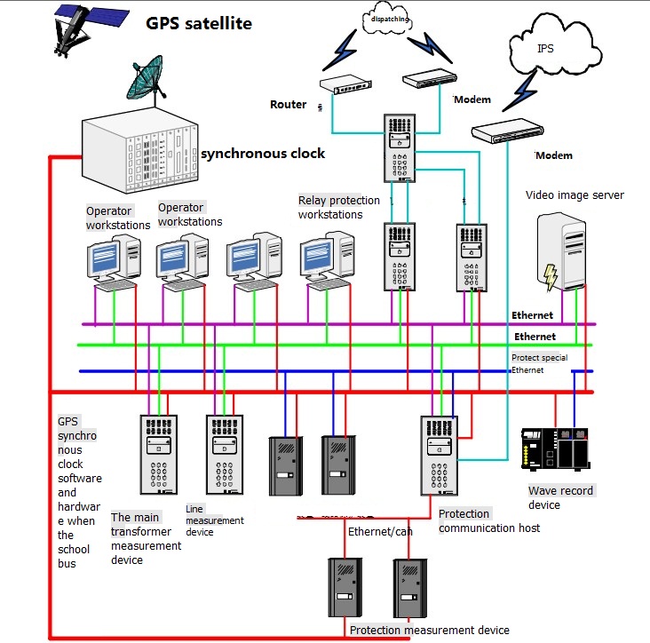
220V Substation Time Synchronization System Typical Configuration
GPS NTP/SNTP Time Server(Silver 2U Chassis)
GPS 2U Chassis NTP time server(GPS Single source)
The series of GPS Standard Time Synchoronous Clock that we manufactured are specifically for power system, automatizatio system, communicate system and traffic system that need high-precise time requirer.Our system is based on GPS, and the precision of time is 1µs. The facility is secondary developed with the GPS receiver that made by the special factory of United States. It can track 12 GPS satellites at the same time, and selects the best satellite automaticly for locating and timing. It outputs 1PPS, 1PPM, 1PPH time pulse and Beijing time ,and the synchronous precision is 1µs, and it can measure the industrial frequency, and outputs date, time, cycle clock, cycle, clock difference, safe running days, and so on through RS232 serial with two formats. It is selected to used by automatization facilities that need standard time in electric power system.The facility adopted the technology of the united of software and hardware, and made good use of the potential of GPS receiver, so it has some characters such as high security, strong function, high precision, good proportion of capability and price, operate conveniently and so on,and it can afford to the requirement of time synchronous in electric power system,automatization system, communicate system and traffic system. With its extendly used, the development of some automatization technologies such as accident analysis, trouble range measurement and relay protection and so on will be promoted and improved greatly.
2 Technical parameter:
1. Receiving frequency:1575.42MHZ, it can track 8-12 GPS satellites at the same time.
2. Antenna radio sentivity:-166dbw, with 30 metres wire. If the wire is not long enough, customer can prolong it by himself by selection of coaxial-cable that attenuation of
1.56GHZ is not more than 0.7db per metre, the attenuation of prolonged cable is not more than 5db.
3. Capture time: from 20 seconds to 2 minutes (Annotate: the outputs of synchronous clock are all isolated by photoelectricity coupling and output 60ns)
4.1PPS output:
Timing varacity: 1µs Voltage: TTL voltage
Polarity: positive pulse Pulse width: about 100ms
Impedence: 50 Ώ Channel number: 1
Fore edge: <20ns
5.1PPM: output:
Timing varacity:: 1µs Voltage: TTL
Polarity: positive pulse Pulse width: about 100ms
Impedence: 50 Ώ Fore edge: <20ns
6.1PPH output:
Timing varacity:: 1µs Voltage: TTL
Polarity: positive pulse Pulse width: about 100ms
Impedence: 50 Ώ Fore edge: <20ns
7.Cycle precision: ±0.001
8.Industry frequency clock: the clock that is promoted by industry electricity is synchronous with standard clock when power is on.
9.Clock difference: that is standard clock minus industry frequency clock,synchronous time difference is zero,precision is 20 ms.
10.Longitude, latitude: where the electric power synchronous clock locates.
11.Display: 14 bits LCD display that includes cycle,date,time,longitude,latitude,industry frequency clock,clock difference (standard clock minus industry frequency clock).
12.RS232: output time code (year, month, day, hour, minute, second), industry frequency clock time(hour, minute, second), clock difference,cycle.
13.RS232: output “ST” format time code (selected by switching circuitry)
14.Power: DC110V, 10%, 15W.
15.Size: standard industry 19 inch 2U box.
Model selection
|
Model |
Technical Parameters
|
Comment (Optional dual power) |
|
SY-GPS-2-G |
2 channel 1 PPS,2 channel 1 PPM , 1 channel 1 PPH (TTL/ active optical isolation and passive) 4 channel RS232, 2 channel RS485 (serial code) 2 "RS485 (IRIG-B (DC) difference), lose electric/out-of-step alarm to the 2 With expand output interface (can direct drive extension device)
|
Ac/dc power supply terminals wide input Optional NTP and optical output
|
|
SY-GPS-2-E16 |
2 channel 1 PPS,2 channel 1 PPM , 1 channel 1 PPH (TTL/ active optical isolation and passive) 4 channel RS232, 2 channel RS485 (serial code) 16channel"RS485 (IRIG-B (DC) difference), lose electric/out-of-step alarm to the 2 With expand output interface (can direct drive extension device)
|
Ac/dc power supply terminals wide input Optional NTP and optical output
|
|
SY-2U-TIME SY-2U-GPS-CPU X1 SY-2EX-IRIG-B(DC) X1 |
12 "RS485 (IRIG-B (DC) difference), lose electric/out-of-step alarm to the 2
|
2Uchassis Can be expanded plug-in |
|
SY-GPS-2-E32 |
2 channel 1 PPS,2 channel 1 PPM , 1 channel 1 PPH (TTL/ active optical isolation and passive) 4 channel RS232, 2 channel RS485 (serial code) 32 "RS485 (IRIG-B (DC) difference), lose electric/out-of-step alarm to the 2 With expand output interface (can direct drive extension device)
|
Ac/dc power supply terminals wide input Optional NTP and optical output
|
|
SY-2U-TIME SY-2U-GPS-CPU X1 SY-2EX-IRIG-B(DC) X3 |
32channel"RS485 (IRIG-B (DC) difference), lose electric/out-of-step alarm to the 2 |
2U chassis Can be expanded plug-in |
|
SY-GPS-2-FS16 (PPS OutPut) |
2 channel 1 PPS,2 channel 1 PPM , 1 channel 1 PPH (TTL/ active optical isolation and passive) 4 channel RS232, 2 channel RS485 (serial code) 2 "RS485 (IRIG-B (DC) difference), 16 channel 1 PPS / 1 PPM high-pressure high-speed photoelectric isolated active and passive output lose electric/out-of-step alarm to the 2 With expand output interface (can direct drive extension device) |
Ac/dc power supply terminals wide input Optional NTP and optical output
|
|
SY-GPS-2-FM16 (PPM ,Pulse Per Minute Output) |
|
|
|
SY-2U-TIME SY-2U-GPS-CPU X1 SY-2EX-1PPS/1PPM X1 |
12 "RS485 (IRIG-B (DC) difference), , lose electric/out-of-step alarm to the 2
|
2U chassis
|
|
SY-GPS-2-FS32(PPS Output) |
2 channel 1 PPS,2 channel 1 PPM , 1 channel 1 PPH (TTL/ active optical isolation and passive) 4 channel RS232, 2 channel RS485 (serial code) 2 "RS485 (IRIG-B (DC) difference), 32 channel 1 PPS / 1 PPM high-pressure high-speed photoelectric isolated active and passive output lose electric/out-of-step alarm to the 2 With expand output interface (can direct drive extension device) |
Ac/dc power supply terminals wide input Optional NTP and optical output
|
|
SY-GPS-2-FM32 (PPM ,Pulse Per Minute Output)) |
|
|
|
SY-2U-TIME SY-2U-GPS-CPU X1 SY-2EX-1PPS/1PPM X3 |
36 "RS485 (IRIG-B (DC) difference), , lose electric/out-of-step alarm to the 2
|
2U chassis |
|
SY-GPS-2-NET |
2 channel 1 PPS,2 channel 1 PPM , 1 channel 1 PPH (TTL/ active optical isolation and passive) 4 channel RS232, 2 channel RS485 (serial code) 2 "RS485 (IRIG-B (DC) difference), lose electric/out-of-step alarm to the 2 With expand output interface (can direct drive extension device) 2 "NTP/TCP network time output
|
Ac/dc power supply terminals wide input. Optional fiber optical output
|
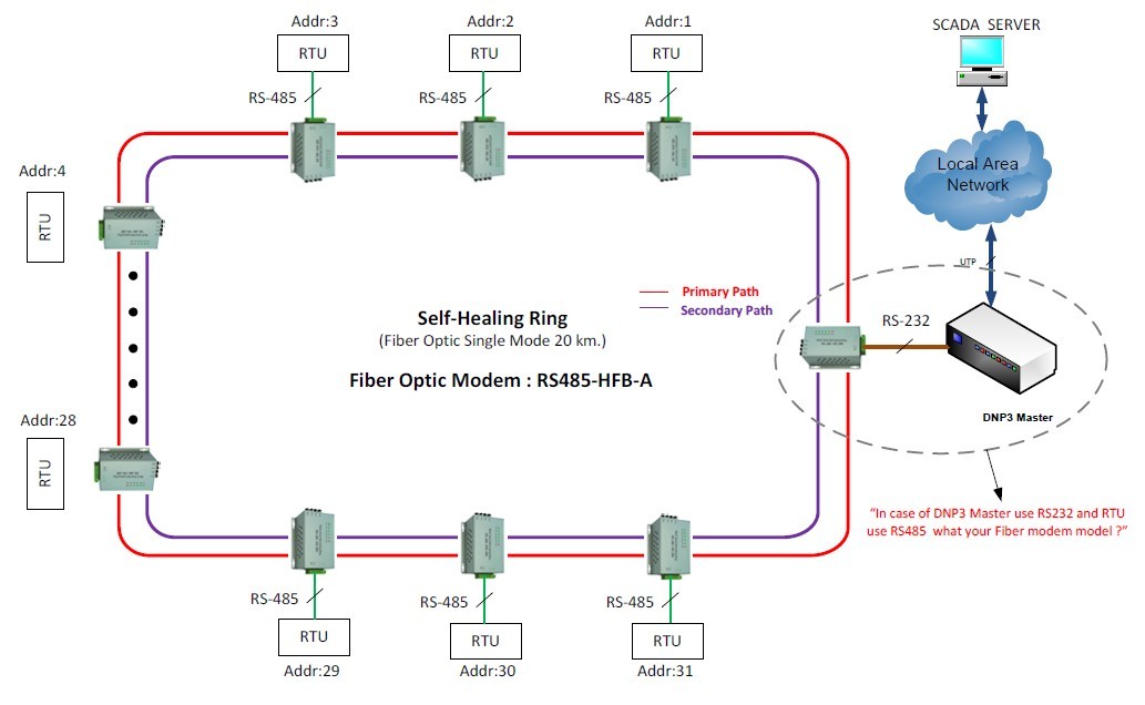
Our 2200 units of Industrial RS485 Fiber Optic Modem into UK Project
Over the past month of May,2012,we just signed a contract with Emersson for the order of 2200 units of industrial grade Rs485 fiber optic modems and our products will be used in their street light project.
What is Lonworks?
Origins and uptake
The technology has its origins with chip designs, power line and twisted pair, signaling technology, routers, network management software, and other products from Echelon Corporation. In 1999 the communications protocol (then known as LonTalk) was submitted to ANSI and accepted as a standard for control networking (ANSI/CEA-709.1-B). Echelon's power line and twisted pair signaling technology was also submitted to ANSI for standardization and accepted. Since then, ANSI/CEA-709.1 has been accepted as the basis for IEEE 1473-L (in-train controls), AAR electro-pneumatic braking systems for freight trains, IFSF (European petrol station control), SEMI (semiconductor equipment manufacturing), and in 2005 as EN 14908 (European building automation standard). The protocol is also one of several data link/physical layers of the BACnet ASHRAE/ANSI standard for building automation.
China ratified the technology as a national controls standard, GB/Z 20177.1-2006 and as a building and intelligent community standard, GB/T 20299.4-2006; and in 2007 CECED, the European Committee of Domestic Equipment Manufacturers, adopted the protocol as part of its Household Appliances Control and Monitoring – Application Interworking Specification (AIS) standards.
During 2008 ISO and IEC have granted the communications protocol, twisted pair signaling technology, power line signaling technology, and Internet Protocol (IP) compatibility standard numbers ISO/IEC 14908-1, -2, -3, and -4.
Usage
By 2010 approximately 90 million devices were installed with LonWorks technology. Manufacturers in a variety of industries including building, home, street lighting, transportation, utility, and industrial automation have adopted the platform as the basis for their product and service offerings. Statistics as to the number of locations using the LonWorks technology are scarce, but it is known that products and applications built on top of the platform include such diverse functions as embedded machine control, municipal and highway/tunnel/street lighting, heating and air conditioning systems, intelligent electricity metering, subway train control, stadium lighting and speaker control, security systems, fire detection and suppression, and newborn location monitoring and alarming.
Technical details
Two physical-layer signaling technologies, twisted pair "free topology" and power line carrier, are typically included in each of the standards created around the LonWorks technology. The two-wire layer operates at 78 kbit/s using differential Manchester encoding, while the power line achieves either 5.4 or 3.6 kbit/s, depending on frequency.[1]
Additionally, the LonWorks platform uses an affiliated IP tunneling standard—ISO/IEC 14908-4[2] (ANSI/CEA-852[3]) -- in use by a number of manufacturers[4] to connect the devices on previously deployed and new LonWorks platform-based networks to IP-aware applications or remote network-management tools. Many LonWorks platform-based control applications are being implemented with some sort of IP integration, either at the UI/application level or in the controls infrastructure. This is accomplished with web services or IP-routing products available in the market.
An Echelon Corporation-designed IC consisting of several 8-bit processors, the "Neuron chip" was initially the only way to implement a LonTalk protocol node and is used in the large majority of LonWorks platform-based hardware. Since 1999, the protocol has been available for general-purpose processors[5]: a port of the ANSI/CEA-709.1 standard to IP-based or 32-bit chips.
Applications using LonWorks
Semiconductor manufacturing,Lighting control systems,Energy management systems,Heating/ventilation/air-conditioning systems,Security systems,Home automation,Consumer appliance controls,Public street lighting, monitoring, and control,Petrol station control,Rail Electronically Controlled Pneumatic Braking
SNVTs (Standard Network Variable Types)
One of the keys to the interoperability of the system is the standardisation of the variables used to describe physical things to LonWorks, this standards list is maintained by LonMark International and each standard is known as Standard Network Variable Types (SNVTs, pronounced "sniv-its") so for example a thermostat using the temperature SNVT is expected to produce a number between zero and 65535 that equates to a temperature between -274 and 6279.5 degrees Celsius.