Sidebar
News Press

Administrator
DeviceNet Fiber Optic Converter(Wall Mount)
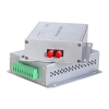
DeviceNet Converter(Point to point & Multi-drop Bus)
Descriptions:
The DeviceNet series products provide an optical point-to-point or bus network connection for DeviceNet data interfaces on one or two, multimode or singlemode optical fibers. The DeviceNet Point-to-Point Transmission units operate as the end or terminal points and provide an electrical connection and a two fibre optical connection. The units support CAN 1.0 and CAN 2.0 CAN standards, and CAN. And are transparent to all high level protocols.
This series is available in either wall mount, DIN rail or 3U chassis card configurations.
Product Features
Up to 1Mbps data rate
Multimode and singlemode
Single fiber solution
Wall mount, rack or chassis configurations
| Data | |
| Data Formats | CAN1.0 ,CAN2.0 , Device Net,CAN Open |
| CAN Data Rate | 0~1Mbps |
| Bit Error Rate | <1 x 10-12 |
| Connectors | |
| Data | Screw Block Terminal |
| Fiber | ST, SC or FC (ST fitted as standard) |
| Environmental | |
| Operating Temperat ure | - 3 0 C--- +70 C |
| Storage Temperature | - 40 C--- +85 C |
| Operating Humidity | 0- 95% |
| MTBF | >100,000 Hours |
| Optical | |
| Fiber | Multimode or singlemode |
| Wavelength | MM: 850nm, SM: 1310nm |
| Number of fibers | 2 or 1 |
| POWER | |
| Power Input | AC 220V 110v or DC+110V +5V +12V +24V +48V Option |
| Mechanical | |
| Dimensions | 125(L)×110(W)×36(H )Wall Mount & DIN Rail |
Ordering information:
|
Model Number |
Description |
Fiber No. |
Fiber Mode |
Fiber Connector |
|
HFB-FO-DEV-P1M |
Point to point Link,Single Fiber(BI-DI), 2km |
1 |
Multi Mode |
ST/SC/FC |
|
HFB-FO-DEV-P2M |
Point to point Link,Dual Fiber, 2km |
2 |
Multi Mode |
ST/SC/FC |
|
HFB-FO-DEV-P1S |
Point to point Link,Single Fiber(BI-DI), 20km |
1 |
Single Mode |
ST/SC/FC |
|
HFB-FO-DEV-P2S |
Point to point Link,Dual Fiber, 20km |
2 |
Single Mode |
ST/SC/FC |
|
HFB-FO-DEV-M2M |
Multi point Link,Dual Fiber(BI-DI), 2km |
2 |
Multi Mode |
ST/SC/FC |
|
HFB-FO-DEV-M4M |
Multi point Link,4 Fiber, 2km |
4 |
Multi Mode |
ST/SC/FC |
|
HFB-FO-DEV-M2S |
Multi point Link,Dual Fiber(BI-DI), 20km |
2 |
Single Mode |
ST/SC/FC |
|
HFB-FO-DEV-M4S |
Multi point Link,4 Fiber, 20km |
4 |
Single Mode |
ST/SC/FC |
CAN Open to Fiber Optic Converter(Wall Mount)
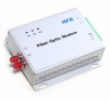
CAN-Open Fiber Optic Converter
Descriptions:
This series is available in either wall mount, DIN rail or 3U chassis card configurations.
Product Features
- Up to 1Mbps data rate
- Multimode and singlemode
- Single fiber solution
- Wall mount, rack or chassis configurations
- Product Features
- Up to 1Mbps data rate
- Multimode and singlemode
- Single fiber solution
- Wall mount, rack or chassis configurations
The CAN Open series products provide an optical point-to-point or bus network connection for CAN Open data interfaces on one or two, multimode or singlemode optical fibers. The CAN Open Point-to-Point Transmission units operate as the end or terminal points and provide an electrical connection and a two fibre optical connection. The units support CAN 1.0 and CAN 2.0 CAN standards, and Device Net. And are transparent to all high level protocols.
| Data | |
| Data Formats | CAN1.0 ,CAN2.0 , Device Net |
| CAN Data Rate | 0~1Mbps |
| Bit Error Rate | <1 x 10-12 |
| Connectors | |
| Data | Screw Block Terminal |
| Fiber | ST, SC or FC (ST fitted as standard) |
| Environmental | |
| Operating Temperat ure | - 3 0 C--- +70 C |
| Storage Temperature | - 40 C--- +85 C |
| Operating Humidity | 0- 95% |
| MTBF | >100,000 Hours |
| Optical | |
| Fiber | Multi mode or single mode |
| Wavelength | MM: 850nm, SM: 1310nm |
| Number of fibers | 2 or 1 |
| POWER | |
| Power Input | AC 220V 110v or DC+110V +5V +12V +24V +48V Option |
| Mechanical | |
| Dimensions | 125(L)×110(W)×36(H )Wall Mount & DIN Rail |
Ordering information:
|
Model Number |
Description |
Fiber No. |
Fiber Mode |
Fiber Connector |
|
HFB-FO-OPE-P1M |
Point to point Link,Single Fiber(BI-DI), 2km |
1 |
Multi Mode |
ST/SC/FC |
|
HFB-FO-OPE-P2M |
Point to point Link,Dual Fiber, 2km |
2 |
Multi Mode |
ST/SC/FC |
|
HFB-FO-OPE-P1S |
Point to point Link,Single Fiber(BI-DI), 20km |
1 |
Single Mode |
ST/SC/FC |
|
HFB-FO-OPE-P2S |
Point to point Link,Dual Fiber, 20km |
2 |
Single Mode |
ST/SC/FC |
|
HFB-FO-OPE-M2M |
Multi point Link,Dual Fiber(BI-DI), 2km |
2 |
Multi Mode |
ST/SC/FC |
|
HFB-FO-OPE-M4M |
Multi point Link,4 Fiber, 2km |
4 |
Multi Mode |
ST/SC/FC |
|
HFB-FO-OPE-M2S |
Multi point Link,Dual Fiber(BI-DI), 20km |
2 |
Single Mode |
ST/SC/FC |
|
HFB-FO-OPE-M4S |
Multi point Link,4 Fiber, 20km |
4 |
Single Mode |
ST/SC/FC |
Isolated Can Bus to Ethernet(TCP/IP) Converter Datasheet
RS-232 to Zigbee Gateway Module
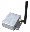
RS232 to Zigbee Wireless Gateway/Module/Converter(BUE-ZIG-232)
1,Description:
ZIGBEE wireless module is full zigbee wireless communication equipment,integrated with zigbee 2.4G RF modem and MCU,excellence with far distance communication, excellently anti-jamming capacity。
The zigbee network is constituted of the center node and access node, the center node is PAN_Coord, the access node is router or end device. you should install the PAN_Coord first, then install the access node
2,Specification:
|
OPTION PERFORMACE PARAMETER |
||
|
wireless |
distance |
2000m |
|
Net topo |
star、line、mesh |
|
|
addressing |
IEEE802.15.4/ZIGBEE standard addressing |
|
|
Anti-collision |
CSMA-CA and GTS CSMA-CA |
|
|
Data interface |
Max packet |
256 byte |
|
interface |
RS232/485 |
|
|
Physical interface |
8-pin RJ45 |
|
|
ESD protection |
15 KV ESD |
|
|
Signal line |
TxD, RxD, GND |
|
|
Baud rate |
1200 ~ 38400 bps |
|
|
Parity type |
None, Even, Odd |
|
|
Data bit |
8, 9 |
|
|
Parity bit |
1 |
|
|
RF MODEM |
modulation |
DSSS (O-QPSK) |
|
frequency |
2.405GHz~ 2.480GHz |
|
|
power |
9V DC |
|
|
channel |
16 |
|
|
RX sensitivity |
-94 dbm |
|
|
RF bandwidth |
250kbps |
|
|
|
RF power out
|
-27dBm~25dBm |
|
antenna |
SMA |
|
|
POWER |
max tx current |
200 mA |
|
Max rx current |
165 mA |
|
|
Hibernate |
10 mA |
|
|
Low power |
110 uA |
|
|
Wake |
56 uA |
|
|
ENVIRONMENT |
Working temperature |
- -40°C ~ 85°C |
|
storage temperature |
- -55°C ~ 125°C |
RS-485 to Zigbee Gateway Module

RS485 to Zigbee Wireless Gateway/Module/Converter(BUE-ZIG-485)
1,Description:
ZIGBEE wireless module is full zigbee wireless communication equipment,integrated with zigbee 2.4G RF modem and MCU,excellence with far distance communication, excellently anti-jamming capacity。
The zigbee network is constituted of the center node and access node, the center node is PAN_Coord, the access node is router or end device. you should install the PAN_Coord first, then install the access node
2,Specifications:
|
OPTION PERFORMACE PARAMETER |
||
|
wireless |
distance |
2000m |
|
Net topo |
star、line、mesh |
|
|
addressing |
IEEE802.15.4/ZIGBEE standard addressing |
|
|
Anti-collision |
CSMA-CA and GTS CSMA-CA |
|
|
Data interface |
Max packet |
256 byte |
|
interface |
RS232/485 |
|
|
Physical interface |
8-pin RJ45 |
|
|
ESD protection |
15 KV ESD |
|
|
Signal line |
TxD, RxD, GND |
|
|
Baud rate |
1200 ~ 38400 bps |
|
|
Parity type |
None, Even, Odd |
|
|
Data bit |
8, 9 |
|
|
Parity bit |
1 |
|
|
RF MODEM |
modulation |
DSSS (O-QPSK) |
|
frequency |
2.405GHz~ 2.480GHz |
|
|
power |
9V DC |
|
|
channel |
16 |
|
|
RX sensitivity |
-94 dbm |
|
|
RF bandwidth |
250kbps |
|
|
|
RF power out
|
-27dBm~25dBm |
|
antenna |
SMA |
|
|
POWER |
max tx current |
200 mA |
|
Max rx current |
165 mA |
|
|
Hibernate |
10 mA |
|
|
Low power |
110 uA |
|
|
Wake |
56 uA |
|
|
ENVIRONMENT |
Working temperature |
- -40°C ~ 85°C |
|
storage temperature |
- -55°C ~ 125°C |
Ethernet to Zigbee Gateway(Module)
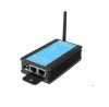
Ethernet to Zigbee Wireless Gateway(BUE-ZIG-TCP)
Ethernet to Zigbee Wireless Converter
1,Description:
ZIGBEE wireless module is full zigbee wireless communication equipment,integrated with zigbee 2.4G RF modem and MCU,excellence with far distance communication, excellently anti-jamming capacity.
The zigbee network is constituted of the center node and access node, the center node is PAN_Coord, the access node is router or end device. you should install the PAN_Coord first, then install the access node
2,Specifications:
|
OPTION PERFORMACE PARAMETER |
||
|
wireless |
distance |
2000m |
|
Net topo |
star、line、mesh |
|
|
addressing |
IEEE802.15.4/ZIGBEE standard addressing |
|
|
Anti-collision |
CSMA-CA and GTS CSMA-CA |
|
|
Data interface |
Max packet |
256 byte |
|
interface |
RS232/485 |
|
|
Physical interface |
8-pin RJ45 |
|
|
ESD protection |
15 KV ESD |
|
|
Signal line |
TxD, RxD, GND |
|
|
Baud rate |
1200 ~ 38400 bps |
|
|
Parity type |
None, Even, Odd |
|
|
Data bit |
8, 9 |
|
|
Parity bit |
1 |
|
|
RF MODEM |
modulation |
DSSS (O-QPSK) |
|
frequency |
2.405GHz~ 2.480GHz |
|
|
power |
9V DC |
|
|
channel |
16 |
|
|
RX sensitivity |
-94 dbm |
|
|
RF bandwidth |
250kbps |
|
|
|
RF power out
|
-27dBm~25dBm |
|
antenna |
SMA |
|
|
POWER |
max tx current |
200 mA |
|
Max rx current |
165 mA |
|
|
Hibernate |
10 mA |
|
|
Low power |
110 uA |
|
|
Wake |
56 uA |
|
|
ENVIRONMENT |
Working temperature |
- -40°C ~ 85°C |
|
storage temperature |
- -55°C ~ 125°C |
TTL to Fiber Optic Converter
Product Description
The data series uses the most advanced digital technologies to provide excellent repeatable performance for today’s data systems. It supports transmission of one bi-directional data channel over one multimode or singlemode optical fiber. RS232, RS422 and RS485 standards are fully supported. The plug-and-play design ensures ease of installation with no electrical or optical adjustment needed. LED indicators are provided to show the operational status of the unit clearly.
The series is available in compact wall mount or 3U chassis card.
The RS-232 Series converter is equipped with a multiple interface circuit that can handle RS-232 serial interfaces and multi-mode or single- mode fiber. RS-232 converters are used to extend serial transmission distance up to 2 km (multi-mode fiber) or up to 20-100km (single- mode fiber). .Auto Baud Rate DetectionThe RS-232 Series incorporates a method for automatically detecting the serial signal baud rate by hardware. This is an extremely convenient feature for the user. Even if a device's baud rate is changed, the signal will still be transmitted through the RS-232 to fiber converter without any problem.
Product Features
Supports RS232, RS422 and RS485
Multimode and singlemode solutions
Switchable 120Ω termination and biasing
LED indicators provide quick diagnosis of all important system parameters
Up to 14 units in a 3U chassis
Compact and 3U chassis card configuration
Specifications
|
Data |
|
|
Data Formats |
RS232,RS422,RS485 |
|
RS232 Data Rate |
115.2kbps |
|
RS422/485 Data Rate |
512kbps or 1Mkbps |
|
Bit Error Rate |
<1 x 10-12 |
|
Connectors |
|
|
Data |
Screw Block Terminal |
|
Fiber |
ST, SC or FC (ST fitted as standard) |
|
Environmental |
|
|
Operating Temperature |
-30C---+70C |
|
Storage Temperature |
-30C---+70C |
|
Operating Humidity |
0-95% |
|
MTBF |
>100,000 Hours |
|
Optical |
|
|
Fiber |
Multimode or Singlemode |
|
Wavelength |
MM:850nm,SM:1310nm |
|
Number of fibers |
2 or 1 |
|
POWER |
|
|
Power Input |
AC 220V 110v or DC+110V,+5V,+12V,+24V,+48V Option |
|
Mechanical |
|
|
Dimensions |
125(L)×110(W)×36(H)Wall Mount & DIN Rail |
Ordering information:
|
Model Number |
Description |
Fiber No. |
Fiber Mode |
Fiber Connector |
|
HFB-FO-TTL-P1M |
Point to point Link,Single Fiber(BI-DI), 2km |
1 |
Multi Mode |
ST/SC/FC |
|
HFB-FO-TTL-P2M |
Point to point Link,Dual Fiber, 2km |
2 |
Multi Mode |
ST/SC/FC |
|
HFB-FO-TTL-P1S |
Point to point Link,Single Fiber(BI-DI), 20km |
1 |
Single Mode |
ST/SC/FC |
|
HFB-FO-TTL-P2S |
Point to point Link,Dual Fiber, 20km |
2 |
Single Mode |
ST/SC/FC |
|
HFB-FO-TTL-M2M |
Multi point Link,Dual Fiber(BI-DI), 2km |
2 |
Multi Mode |
ST/SC/FC |
|
HFB-FO-TTL-M4M |
Multi point Link,4 Fiber, 2km |
4 |
Multi Mode |
ST/SC/FC |
|
HFB-FO-TTL-M2S |
Multi point Link,Dual Fiber(BI-DI), 20km |
2 |
Single Mode |
ST/SC/FC |
|
HFB-FO-TTL-M4S |
Multi point Link,4 Fiber, 20km |
4 |
Single Mode |
ST/SC/FC |
Ethernet Fiber Media Converters Datasheet
The Knowledge About SCADA
SCADA (supervisory control and data acquisition) generally refers to industrial control systems (ICS): computer systems that monitor and control industrial, infrastructure, or facility-based processes, as described below:
- Industrial processes include those of manufacturing, production, power generation, fabrication, and refining, and may run in continuous, batch, repetitive, or discrete modes.
- Infrastructure processes may be public or private, and include water treatment and distribution, wastewater collection and treatment, oil and gas pipelines, electrical power transmission and distribution, wind farms, civil defense siren systems, and large communication systems.
- Facility processes occur both in public facilities and private ones, including buildings, airports, ships, and space stations. They monitor and control HVAC, access, and energy consumption.
Common system components
A SCADA system usually consists of the following subsystems:
- A human–machine interface or HMI is the apparatus which presents process data to a human operator, and through this, the human operator monitors and controls the process.
- A supervisory (computer) system, gathering (acquiring) data on the process and sending commands (control) to the process.
- Remote terminal units (RTUs) connecting to sensors in the process, converting sensor signals to digital data and sending digital data to the supervisory system.
- Programmable logic controller (PLCs) used as field devices because they are more economical, versatile, flexible, and configurable than special-purpose RTUs.
- Communication infrastructure connecting the supervisory system to the remote terminal units.
- Various process and analytical instrumentation
Supervision versus control
There is, in several industries, considerable confusion over the differences between SCADA systems and distributed control systems (DCS). Generally speaking, a SCADA system always refers to a system that coordinates, but does not control processes in real time. The discussion on real-time control is muddied somewhat by newer telecommunications technology, enabling reliable, low latency, high speed communications over wide areas. Most differences between SCADA and DCS are culturally determined and can usually be ignored. As communication infrastructures with higher capacity become available, the difference between SCADA and DCS will fade.
Summary
- DCS is process oriented, while SCADA is data acquisition oriented.
- DCS is process driven, while SCADA is event driven.
- DCS is commonly used to handle operations on a single locale, while SCADA is preferred for applications that are spread over a wide geographic location.
Systems concepts
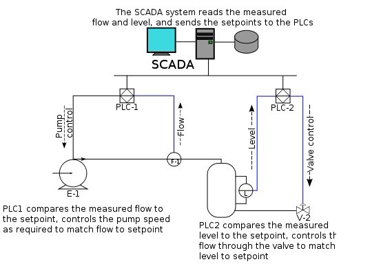
The term SCADA usually refers to centralized systems which monitor and control entire sites, or complexes of systems spread out over large areas (anything from an industrial plant to a nation). Most control actions are performed automatically by RTUs or by PLCs. Host control functions are usually restricted to basic overriding or supervisory level intervention. For example, a PLC may control the flow of cooling water through part of an industrial process, but the SCADA system may allow operators to change the set points for the flow, and enable alarm conditions, such as loss of flow and high temperature, to be displayed and recorded. The feedback control loop passes through the RTU or PLC, while the SCADA system monitors the overall performance of the loop.
Data acquisition begins at the RTU or PLC level and includes meter readings and equipment status reports that are communicated to SCADA as required. Data is then compiled and formatted in such a way that a control room operator using the HMI can make supervisory decisions to adjust or override normal RTU (PLC) controls. Data may also be fed to a Historian, often built on a commodity Database Management System, to allow trending and other analytical auditing.
SCADA systems typically implement a distributed database, commonly referred to as a tag database, which contains data elements called tags or points. A point represents a single input or output value monitored or controlled by the system. Points can be either "hard" or "soft". A hard point represents an actual input or output within the system, while a soft point results from logic and math operations applied to other points. (Most implementations conceptually remove the distinction by making every property a "soft" point expression, which may, in the simplest case, equal a single hard point.) Points are normally stored as value-timestamp pairs: a value, and the timestamp when it was recorded or calculated. A series of value-timestamp pairs gives the history of that point. It's also common to store additional metadata with tags, such as the path to a field device or PLC register, design time comments, and alarm information.
Human–machine interface
A human–machine interface or HMI is the apparatus which presents process data to a human operator, and through which the human operator controls the process.
An HMI is usually linked to the SCADA system's databases and software programs, to provide trending, diagnostic data, and management information such as scheduled maintenance procedures, logistic information, detailed schematics for a particular sensor or machine, and expert-system troubleshooting guides.
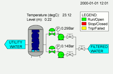
The HMI system usually presents the information to the operating personnel graphically, in the form of a mimic diagram. This means that the operator can see a schematic representation of the plant being controlled. For example, a picture of a pump connected to a pipe can show the operator that the pump is running and how much fluid it is pumping through the pipe at the moment. The operator can then switch the pump off. The HMI software will show the flow rate of the fluid in the pipe decrease in real time. Mimic diagrams may consist of line graphics and schematic symbols to represent process elements, or may consist of digital photographs of the process equipment overlain with animated symbols.
The HMI package for the SCADA system typically includes a drawing program that the operators or system maintenance personnel use to change the way these points are represented in the interface. These representations can be as simple as an on-screen traffic light, which represents the state of an actual traffic light in the field, or as complex as a multi-projector display representing the position of all of the elevators in a skyscraper or all of the trains on a railway.
An important part of most SCADA implementations is alarm handling. The system monitors whether certain alarm conditions are satisfied, to determine when an alarm event has occurred. Once an alarm event has been detected, one or more actions are taken (such as the activation of one or more alarm indicators, and perhaps the generation of email or text messages so that management or remote SCADA operators are informed). In many cases, a SCADA operator may have to acknowledge the alarm event; this may deactivate some alarm indicators, whereas other indicators remain active until the alarm conditions are cleared. Alarm conditions can be explicit—for example, an alarm point is a digital status point that has either the value NORMAL or ALARM that is calculated by a formula based on the values in other analogue and digital points—or implicit: the SCADA system might automatically monitor whether the value in an analogue point lies outside high and low limit values associated with that point. Examples of alarm indicators include a siren, a pop-up box on a screen, or a coloured or flashing area on a screen (that might act in a similar way to the "fuel tank empty" light in a car); in each case, the role of the alarm indicator is to draw the operator's attention to the part of the system 'in alarm' so that appropriate action can be taken. In designing SCADA systems, care is needed in coping with a cascade of alarm events occurring in a short time, otherwise the underlying cause (which might not be the earliest event detected) may get lost in the noise. Unfortunately, when used as a noun, the word 'alarm' is used rather loosely in the industry; thus, depending on context it might mean an alarm point, an alarm indicator, or an alarm event.
Hardware solutions
SCADA solutions often have distributed control system (DCS) components. Use of "smart" RTUs or PLCs, which are capable of autonomously executing simple logic processes without involving the master computer, is increasing. A standardized control programming language, IEC 61131-3 (a suite of 5 programming languages including Function Block, Ladder, Structured Text, Sequence Function Charts and Instruction List), is frequently used to create programs which run on these RTUs and PLCs. Unlike a procedural language such as the C programming language or FORTRAN, IEC 61131-3 has minimal training requirements by virtue of resembling historic physical control arrays. This allows SCADA system engineers to perform both the design and implementation of a program to be executed on an RTU or PLC. A programmable automation controller (PAC) is a compact controller that combines the features and capabilities of a PC-based control system with that of a typical PLC. PACs are deployed in SCADA systems to provide RTU and PLC functions. In many electrical substation SCADA applications, "distributed RTUs" use information processors or station computers to communicate with digital protective relays, PACs, and other devices for I/O, and communicate with the SCADA master in lieu of a traditional RTU.
Since about 1998, virtually all major PLC manufacturers have offered integrated HMI/SCADA systems, many of them using open and non-proprietary communications protocols. Numerous specialized third-party HMI/SCADA packages, offering built-in compatibility with most major PLCs, have also entered the market, allowing mechanical engineers, electrical engineers and technicians to configure HMIs themselves, without the need for a custom-made program written by a software developer.
Remote terminal unit
The RTU connects to physical equipment. Typically, an RTU converts the electrical signals from the equipment to digital values such as the open/closed status from a switch or a valve, or measurements such as pressure, flow, voltage or current. By converting and sending these electrical signals out to equipment the RTU can control equipment, such as opening or closing a switch or a valve, or setting the speed of a pump. It can also control the flow of a liquid.
Supervisory station
The term supervisory station refers to the servers and software responsible for communicating with the field equipment (RTUs, PLCs, etc.), and then to the HMI software running on workstations in the control room, or elsewhere. In smaller SCADA systems, the master station may be composed of a single PC. In larger SCADA systems, the master station may include multiple servers, distributed software applications, and disaster recovery sites. To increase the integrity of the system the multiple servers will often be configured in a dual-redundant or hot-standby formation providing continuous control and monitoring in the event of a server failure.
Operational philosophy
For some installations, the costs that would result from the control system failing are extremely high. Possibly even lives could be lost. Hardware for some SCADA systems is ruggedized to withstand temperature, vibration, and voltage extremes. In the most critical installations, reliability is enhanced by having redundant hardware and communications channels, up to the point of having multiple fully equipped control centres. A failing part can be quickly identified and its functionality automatically taken over by backup hardware. A failed part can often be replaced without interrupting the process. The reliability of such systems can be calculated statistically and is stated as the mean time to failure, which is a variant of mean time between failures. The calculated mean time to failure of such high reliability systems can be on the order of centuries.
Communication infrastructure and methods
SCADA systems have traditionally used combinations of radio and direct wired connections, although SONET / SDH is also frequently used for large systems such as railways and power stations. The remote management or monitoring function of a SCADA system is often referred to as telemetry. Some users want SCADA data to travel over their pre-established corporate networks or to share the network with other applications. The legacy of the early low-bandwidth protocols remains, though.
SCADA protocols are designed to be very compact. Many are designed to send information only when the master station polls the RTU. Typical legacy SCADA protocols include Modbus RTU, RP-570, Profibus and Conitel. These communication protocols are all SCADA-vendor specific but are widely adopted and used. Standard protocols are IEC 60870-5-101 or 104, IEC 61850 and DNP3. These communication protocols are standardized and recognized by all major SCADA vendors. Many of these protocols now contain extensions to operate over TCP/IP.
Although some believe it is good security engineering practice to avoid connecting SCADA systems to the Internet so the attack surface is reduced, many industries, such as wastewater collection and water distribution, have used existing cellular networks to monitor their infrastructure along with internet portals for end-user data delivery and modification. Cellular network data is encrypted before transmission over the Internet.
With increasing security demands ( such as North American Electric Reliability Corporation (NERC) and critical infrastructure protection (CIP) in the US), there is increasing use of satellite-based communication. This has the key advantages that the infrastructure can be self contained (not using circuits from the public telephone system), can have built-in encryption, and can be engineered to the availability and reliability required by the SCADA system operator. Earlier experiences using consumer-grade VSAT were poor. Modern carrier-class systems provide the quality of service required for SCADA.
RTUs and other automatic controller devices were developed before the advent of industry wide standards for interoperability. The result is that developers and their management created a multitude of control protocols. Among the larger vendors, there was also the incentive to create their own protocol to "lock in" their customer base. A list of automation protocols is being compiled here.
Recently, OLE for process control (OPC) has become a widely accepted solution for intercommunicating different hardware and software, allowing communication even between devices originally not intended to be part of an industrial network.
Security issues
The move from proprietary technologies to more standardized and open solutions together with the increased number of connections between SCADA systems and office networks and the Internet has made them more vulnerable to attacks—see references. Consequently, the security of some SCADA-based systems has come into question as they are seen as potentially vulnerable to cyber attacks.
In particular, security researchers are concerned about:
- the lack of concern about security and authentication in the design, deployment and operation of some existing SCADA networks
- the belief that SCADA systems have the benefit of security through obscurity through the use of specialized protocols and proprietary interfaces
- the belief that SCADA networks are secure because they are physically secured
- the belief that SCADA networks are secure because they are disconnected from the Internet.
SCADA systems are used to control and monitor physical processes, examples of which are transmission of electricity, transportation of gas and oil in pipelines, water distribution, traffic lights, and other systems used as the basis of modern society. The security of these SCADA systems is important because compromise or destruction of these systems would impact multiple areas of society far removed from the original compromise. For example, a blackout caused by a compromised electrical SCADA system would cause financial losses to all the customers that received electricity from that source. How security will affect legacy SCADA and new deployments remains to be seen.
There are two distinct threats to a modern SCADA system. First is the threat of unauthorized access to the control software, whether it be human access or changes induced intentionally or accidentally by virus infections and other software threats residing on the control host machine. Second is the threat of packet access to the network segments hosting SCADA devices. In many cases, there is rudimentary or no security on the actual packet control protocol, so anyone who can send packets to the SCADA device can control it. In many cases SCADA users assume that a VPN is sufficient protection and are unaware that physical access to SCADA-related network jacks and switches provides the ability to totally bypass all security on the control software and fully control those SCADA networks. These kinds of physical access attacks bypass firewall and VPN security and are best addressed by endpoint-to-endpoint authentication and authorization such as are commonly provided in the non-SCADA world by in-device SSL or other cryptographic techniques.
The reliable function of SCADA systems in our modern infrastructure may be crucial to public health and safety. As such, attacks on these systems may directly or indirectly threaten public health and safety. Such an attack has already occurred, carried out on Maroochy Shire Council's sewage control system in Queensland, Australia. Shortly after a contractor installed a SCADA system there in January 2000 system components began to function erratically. Pumps did not run when needed and alarms were not reported. More critically, sewage flooded a nearby park and contaminated an open surface-water drainage ditch and flowed 500 meters to a tidal canal. The SCADA system was directing sewage valves to open when the design protocol should have kept them closed. Initially this was believed to be a system bug. Monitoring of the system logs revealed the malfunctions were the result of cyber attacks. Investigators reported 46 separate instances of malicious outside interference before the culprit was identified. The attacks were made by a disgruntled employee of the company that had installed the SCADA system. The employee was hoping to be hired full time to help solve the problem.
Many vendors of SCADA and control products have begun to address the risks posed by unauthorized access by developing lines of specialized industrial firewall and VPN solutions for TCP/IP-based SCADA networks as well as external SCADA monitoring and recording equipment.Additionally, application whitelisting solutions are being implemented because of their ability to prevent malware and unauthorized application changes without the performance impacts of traditional antivirus scans.Also, the ISA Security Compliance Institute (ISCI) is emerging to formalize SCADA security testing starting as soon as 2009. ISCI is conceptually similar to private testing and certification that has been performed by vendors since 2007. Eventually, standards being defined by ISA99 WG4 will supersede the initial industry consortia efforts, but probably not before 2011.
The increased interest in SCADA vulnerabilities has resulted in vulnerability researchers discovering vulnerabilities in commercial SCADA software and more general offensive SCADA techniques presented to the general security community. In electric and gas utility SCADA systems, the vulnerability of the large installed base of wired and wireless serial communications links is addressed in some cases by applying bump-in-the-wire devices that employ authentication and Advanced Encryption Standard encryption rather than replacing all existing nodes.
In June 2010, VirusBlokAda reported the first detection of malware that attacks SCADA systems (Siemens' WinCC/PCS7 systems) running on Windows operating systems. The malware is called Stuxnet and uses four zero-day attacks to install a rootkit which in turn logs in to the SCADA's database and steals design and control files.The malware is also capable of changing the control system and hiding those changes. The malware was found by an anti-virus security company on 14 systems, the majority of which were located in Iran.
BUENOPTIC Fiber Optic Converters products all support SCADA systems.
About DeviceNet
DeviceNet is a network system used in the automation industry to interconnect control devices for data exchange. It uses Controller Area Network as the backbone technology and defines an application layer to cover a range of device profiles. Typical applications include information exchange, safety devices, and large I/O control networks.
DeviceNet was originally developed by American company Allen-Bradley (now owned by Rockwell Automation). It is layered on top of the CAN (Controller Area Network) technology, developed by Bosch.DeviceNet adapts the technology from ControlNet, which is another industrial protocol developed by Allen -Bradley, and takes advantage of CAN, making it low-cost and robust compared to the traditional RS-485 based protocols.
In order to promote the use of DeviceNet worldwide, Rockwell Automation has adopted the "open" concept and decided to share the technology to third party vendors. Hence, it is now managed by the Open DeviceNet Vendors Association (ODVA), an independent organization located in North America. ODVA maintains specifications of DeviceNet and oversees advances to DeviceNet. In addition, ODVA ensures compliance to DeviceNet standards by providing conformance testing and vendor conformity.
ODVA later decided to bring DeviceNet back to its predecessor's umbrella and collectively call the technology as Common Industrial Protocol or (CIP), which includes the following technologies:
- EtherNet/IP (take note of the capital 'N', and "IP" here means "Industrial Protocol")
- ControlNet
- DeviceNet
- CompoNet
ODVA claims high integrity between the three technologies due to the common protocol adaptation, which makes industrial controls much simpler compared to other technologies.
Technical Snapshot
- Defines the Media, Physical, Data-Link, and Application layers of the ISO/OSI 7-layer model
- Incorporates trunkline topology with separate buses for signal and power (Typical configuration: two twisted pairs and a single shield)
- Baudrates defined: 125 kbit/s, 250 kbit/s, and 500 kbit/s
- Trunk length is inversely proportional to the speed, i.e. 500, 250 and 100 meters respectively
- A not-so new flat cable was added to the specification to allow the use of the quick-fix connector
- Up to 64 nodes on a single logical network. (Node addresses range from 0 - 63) The network has a low node priority scheme
- Supports master/slave as well as peer-to-peer communication, although majority of the devices work in the master/slave configuration
- Allows multiple masters on a single logical network
- Network cable can supply device power along same cable as communication cable (Generally smaller devices such as photo-eyes, limit switches, and proximity switches).
- Networked devices can be simultaneously controlled and configured
- Engineered to withstand noisy environments
- Supports 4 message types to/from slave devices (Strobed, Polled, Cyclic, COS (change of state)). Some devices support more than 1 message type
Architecture
Physical Layer
Nodes are distributed along a DeviceNet network by the means of a trunkline-dropline topology. This topology allows for ease in wiring and access to the network from multiple taps. In addition, nodes can be easily removed and added to reduce production downtime, increase network flexibility, and decrease troubleshooting time. Since the physical layer is optically isolated from device, communication power and device power can share the same bus (Further reducing the complexity of the network and components within). ( Introduction)
DeviceNet supports 125 kbit/s, 250 kbit/s and 500 kbit/s data rates. Depending on the chosen cable type, DeviceNet can support communication up to 500 meters (Round thick cable). Typical round cable supports up to 100 meters. While flat style cable supports up to 380 meters at 125 kbit/s and 75 meters at 500 kbit/s.( Physical Layer )
Data Link Layer
DeviceNet uses a differential serial bus (Controller Area Network) as its Data Link Layer. Using CAN as a backbone, DeviceNet requires minimal bandwidth to transmit and package messages. In addition, a smaller processor may be selected in the design of device thanks to data frame format and the ease at which the processor can parse through the data. See below for full format.( The Data Link Layer)
CAN Data Frame Format
1 Bit      => Start of Frame
11 Bits    => Identifier
1 Bit      => RTR Bit
6 Bits     => Control Field
0-8 Bytes  => Data Field
15 Bits    => CRC Sequence
1 Bit      => CRC Delimiter
1 Bit      => Acknowledge
1 Bit      => Ack Delimiter
7 Bits     => End of Frame
>2 Bits    => Interframe Space
Reference: Table: Data Frame Format.
Upon transmitting the first packet of data, the "Start of Frame" bit is sent to synchronize all receivers on the network. The CAN identifier (denoted from 0-63) and RTR bit combine to set priority at which the data can be accessed or changed. Lower identifiers have priority over higher identifiers. In addition to transmitting this data to other devices, the device also monitors the data sent. This redundancy validates the data transmitted and eliminates simultaneous transmissions. If a node is transmitting at the same time as another node, the node with the lower 11 bit identifier will continue to transmit while the device with the higher 11 bit identifier will stop.(Introduction & Physical Layer.)
The following 6 bits contain information for specifying the Control Field. The initial two bits are fixed, while the last four are used to specify length field of the Data Field. The Data Field contains from zero to eight bytes of usable data.(Physical Layer.)
The following data frame is the CRC (Cyclic Redundancy Check) Field. The frame consists of 15 bits to detect frame errors and maintains numerous format delimiters. Due to ease of implementation and immunity to most noisy networks, CAN provides a high level of error checking and fault confinement.(Physical Layer.)
Network
DeviceNet incorporates a connection-based network. A connection must initially be established by either an UCMM (Unconnected Message Manager) or a Group 2 Unconnected Port. From there, Explicit and Implicit messages can be sent and received. Explicit messages are packets of data that general require a response from another device. Typical messages are configurations or non-time sensitive data collection. Implicit messages are packets of data that are time critical and generally communicate real-time data over the network. An Explicit Message Connection has to be used to established first before an Implicit Message Connection is made. Once the connection is made, the CAN identifier routes data to the corresponding node.(The Network and Transport Layers.)
Conformance Test
To declare your product as DeviceNet compatible, a vendor needs to send their product to the ODVA test lab for the certification. ODVA used to have a few other test labs around the world, i.e. UK, Japan, and China. It has since been consolidated into one facility in North America.
A full-test version is called the Composite test. It consists of:
- Conformance test. Test against the protocol specification.
- Interoperability test. Test against devices from various vendors on a single, fully populated, network.
Conformance Test Procedure
The following procedure shows you how to get your product certified.
- Register as vendor with ODVA. You will be given a vendor ID.
- Purchase a copy of the DeviceNet specification. A hard and soft copy will be sent to you.
- Purchase the conformance test software and corresponding hardware interface card. Note that only selected interface cards from a few vendors can be used.
- Develop and test product in-house. You would probably need help from the discussion group, see the External links below.
- Submit your product to ODVA test lab for independent verification.
- Repeat the above two steps until your product successfully pass the independent test.