Sidebar
News Press

Administrator
2013 Communicasia Exhibition Held in Singapore--Welcome to Visit our Booth
Bueno will attend Communicasia exhibition held in Singapore in 2013. During the exhibition,Bueno will display the industrial communication products including Profibus OLM, Canbus/Ethernet/Serial/Lonworks fiber optic interfaces,Industrial Ethernet switches, GPS time clocks,Video fiber optic converter, Hubs and so on.We warmly welcome customers from Asia to visit our booth-(booth No.BT6-08).
About Communicasia
CommunicAsia2013 Exhibition
Date: 18 – 21 June 2013
Venue: Basement 2, Levels 1 & 3, Marina Bay Sands, Singapore
Opening Hours: 18 – 20 June, 10.30am – 6pm / 21 June, 10.30am – 4pm
CommunicAsia2013 Summit
Date: 18 – 21 June 2013
Venue: Level 3, Marina Bay Sands, Singapore
Admission
Admission is restricted to trade professionals only and there is no charge to visit the exhibition.
To register for a visitor badge to visit the exhibition, you can do so online before show days, or at Marina Bay Sands, Singapore on show days (18 – 21 June 2013) with your business card.
Visitor badges are non-transferable due to security reasons. You may be asked by security personnel to present proof of identification before entry into the exhibition.
Minors aged 16 years and below will not be allowed entry into exhibition halls.
The Organiser reserves the right to refuse admission to visitors who are not appropriately dressed or do not fulfill admission requirements.
Attire
- All visitors must be in proper attire. Those in shorts, flip-flops / slippers will not be allowed entry into the exhibition and conference.
- The Organiser reserves the right to refuse admission to visitors who are not appropriately dressed or do not fulfill admission requirements.
Organiser
About Singapore Exhibition Services Pte Ltd
Set up in 1976, Singapore Exhibition Services (SES) has established itself as one of the most innovative and respected exhibition and conference organisers in Asia. A pioneer in the Singapore exhibition industry, SES events have served as important platforms for companies aiming to forge new business contacts in Asia. With a portfolio of international tradeshows already serving the Communications, Engineering, Machinery and Lifestyle industries, SES continues to develop new events to meet market needs. SES events consistently attract a high level of overseas participation with foreign exhibitors accounting for almost 80% of the show floor. SES is a member of Allworld Exhibitions Alliance, a global network with over 50 offices worldwide.
For more information, please visit www.sesallworld.com.
Singapore Exhibition Services (SES) – A bizSAFE Level 3 enterprise
Singapore Exhibition Services (SES) attained the status of a bizSAFE Level 3 enterprise in September 2011. A nation-wide initiative launched by the Workplace Safety and Health Council (WSHC) to advocate a safe and healthy workplace, bizSAFE is a thorough programme that assists companies build up their workplace safety and health (WSH) capabilities to reach certified standards.
CommunicAsia is part of Asia’s Largest Infocomm & Media Business Platform
About the Infocomm Media Business Exchange – imbX
imbX is Asia’s largest infocomm and media event that fortifies Singapore’s position as a leading infocomm and media hub. imbX brings together business leaders, companies and industry professionals to showcase their latest innovations, network, exchange ideas and tap new markets. Held annually in Singapore in the month of June, imbX incorporates CommunicAsia, BroadcastAsia, EnterpriseIT and inter-government meetings such as the imbX Ministerial Forum on ICT.
imbX is jointly organised by Singapore Exhibition Services and the Singapore infocomm Technology Federation, and is hosted by the Infocomm Development Authority of Singapore (iDA) and the Media Development Authority of Singapore (MDA).
Redundant Dual Power GPS IRIG-B Time Server
GPS IRIG B Time Server with Redundant Dual Power Supplies:
GPS Standard Time Synchoronous Clock are specifically for power system, automatizatio system, communicate system and traffic system that need high-precise time requirer.Our system is based on GPS or Beidou, and the precision of time is 1µs.The facility is secondary developed with the GPS receiver that made by the special factory of United States. It can track 12 GPS satellites at the same time, and selects the best satellite automaticly for locating and timing. It outputs 1PPS, 1PPM, 1PPH time pulse and UTC time ,and the synchronous precision is 1µs, and it can measure the industrial frequency, and outputs date, time, cycle clock, cycle, clock difference, safe running days, and so on through RS232 serial with two formats. It is selected to used by automatization facilities that need standard time in electric power system.The facility adopted the technology of the united of software and hardware, and made good use of the potential of GPS receiver, so it has some characters such as high security, strong function, high precision, good proportion of capability and price, operate conveniently and so on,and it can afford to the requirement of time synchronous in electric power system,automatization system, communicate system and traffic system. With its extendly used, the development of some automatization technologies such as accident analysis, trouble range measurement and relay protection and so on will be promoted and improved greatly.
2 Technical parameter:
1. Receiving frequency:1575.42MHZ, it can track 8-12 GPS satellites at the same time.
2. Antenna radio sentivity:-166dbw, with 30 metres wire. If the wire is not long enough, customer can prolong it by himself by selection of coaxial-cable that attenuation of 1.56GHZ is not more than 0.7db per metre, the attenuation of prolonged cable is not more than 5db.
3. Capture time: from 20 seconds to 2 minutes (Annotate: the outputs of synchronous clock are all isolated by photoelectricity coupling and output 60ns)
4. 12 to 36 Channels of IRIG-B time code output:
IRIG B (RS485 Terminal) Output: Standard IRIG B002 serial demodulated time code IAW IRIG Standard 200-98.Each outputs is capable of driving a 50 ohm load and each output can drive up to five devices each. All outputs are short circuit protected. The SY-2U-TIME is compatible with the ITS Model 490-D20 IRIG Distribution Amplifier.
Status and Clock Outputs TTL: Standard TTL levels
OC(open Collector): Mosfet, Max Voltage: 100V
Max current: 1.3A, On resistance at 1.3A: 0.3 Ohm,
Max Drain-Source leakage: 500 nA.
5.1PPS output:
Timing varacity: 1µs Voltage: TTL voltage
Polarity: positive pulse Pulse width: about 100ms
Impedence: 50 Ώ Channel number: 1
Fore edge: <20ns
6.1PPM: output:
Timing varacity:: 1µs Voltage: TTL
Polarity: positive pulse Pulse width: about 100ms
Impedence: 50 Ώ Fore edge: <20ns
7.1PPH output:
Timing varacity:: 1µs Voltage: TTL
Polarity: positive pulse Pulse width: about 100ms
Impedence: 50 Ώ Fore edge: <20ns
8.Cycle precision: ±0.001
9.Industry frequency clock: the clock that is promoted by industry electricity is synchronous with standard clock when power is on.
10.Clock difference: that is standard clock minus industry frequency clock,synchronous time difference is zero,precision is 20 ms.
11.Longitude, latitude: where the electric power synchronous clock locates.
12.Display: 14 bits LCD display that includes cycle,date,time,longitude,latitude,industry frequency clock,clock difference (standard clock minus industry frequency clock).
13.RS232: output time code (year, month, day, hour, minute, second), industry frequency clock time(hour, minute, second), clock difference,cycle.
14.RS232: output “ST” format time code (selected by switching circuitry)
15.Power: AC110-220V or DC12-48V, 10%, 15W.
16.Size: standard industry 19 inch 2U box.1U and 3U can also be made.
17. We accept OEM orders for small quantity.
18. Redundant 2 power supplies,it can restart in 10us when 1 power supply is off.
CAN Hub
CAN BUS Hubs(BUE-CAN-HUB)
RS-485 Hub(Black Color)
RS-485 Hub(Black Color)(BUE-485B-HUB)
The BUE-485B-HUB series Star HUB transforms RS-485 Bus into star topology or stelliform topology. Viz. transform two ways RS485 bus input into N(2--24) ways RS485 bus output, and the installation will be quite simple. This enables RS485 bus technology to be quite flexible. The product transforms long-distance distributed nodes, slave devices, and a master device into a dependable RS-485 bus network.Either RS-232 or RS-485 protocol is available. It supports POLLING Protocol. This product is a simple interface converter. It is transparent and compatible with all upper protocol levels.
The Star HUB can be widely used, such as Industrial Controls, Intelligent Transportation Systems (ITS), Industrial Networking, Supervisory Control and Data (SCADA) and so on.
1.2 Technical Specification
- DATA Number of Channels: 2( Input ); 16( Output )
- Interface: TIA/EIA-485
- RS-485 Working Rate: 0 ~ 500Kbps
- RS-485 Distance: 0 ~ 1200m
- Maximum Interface Access Nodes Number: 128
- Connector Type: Terminal
GENERAL
- Operating Temperature: -30 ~ 70˚C / -30 ~ +158ºF
- Operating Humidity: 0 ~ 95% non-condensing
- Mean Time Between Failure (MTBF): > 70,000hrs
- Power Supply Adaptor: AC,DC 220V/110V,24V,12V,+5V
- Enclosure Color: Silver
- Dimensions (Wall mount: L× W×H) 340mm(L) X 170mm(W) x 44mm(H) The size depends on RS485 port number.
Modbus RS-485 Fiber Optic Converter
Modbus RS-485 Fiber Optic Converter
Description:
Transmission rate
The HFD-FO-MB Series Modbus fiber optic converters support all the transmission speeds between 0 ~ 115.2Kbbps.The transmission rate is set automatically as soon as the HFD receives a frame. The HFD system is a high transparent low-latency transmission system, this system in many aspects has excellent performance.The fiber-optic repeater HFD supports the any rate.
Signal regeneration
The modules regenerate the signal form and amplitude of the data received. This allows up to 200 HFD Modbus converter to be cascaded.
Segment monitoring at the RS 485 port
Each receiver monitors the RS 485 bus segment connected to it for faulty frames or continuously busy networks. If faulty frames are received by the receiver, or if the network is busy for longer than the maximum permitted send time, forwarding of the received signals is blocked until frames can be received again correctly.
Segment monitoring at the optical line
Each receiver monitors the optical line port connected to it for recive framesand status. If faulty frames are received by the receiver, or no single for longer than the maximum permitted time, forwarding of the received signals is blocked until the port status is ok,frames can be received again correctly.
Network Topologies of the Modbus Fiber Optic Converter
The following network topologies can be realized with the HFD Modbus optical converter:
_ Point-to-point topology
_ Multi-drop BUS topology
_ Star topology
_ Redundant ring(DSHR)
Combinations of these basic types are also possible. Lines with two optical fibers are used to create the fiber links for these network topologies.If a malfunction – e.g. a break in a fiber line – makes a high degree of field bus network fail-safety necessary, the availability of the network can be increased using a redundant network configuration.
Line topology
In a line structure, the individual RS485 HFDs are connected together by dual-fiber optical fibers. Modules with one optical port are sufficient at the beginning and end of a line, between which modules with two optical ports are necessary.
If single point-to-point connections are to be built up, this can be achieved using two modules each with one optical port.
Star topology
Several modules are combined to form an active RS485 star coupler. Other modules are connected to this by dual-fiber optical fiber lines. The modules of the star coupler are connected to
one another via the electrical port(electrical star segment).All HFD types for different fiber types can be combined using the electrical star segment.
Modules with one or two optical ports can be used to create an active RS485 star coupler. Modules with one optical port are sufficient for connecting a terminal or an RS 485 bus segment to the active star coupler.
Redundant optical ring
This network topology represents a special form of line topology. A high degree of network operating safety is achieved by ”closing“ the optical line. A redundant optical ring can only be realized with modules with two optical ports of the same type.
An interruption of one or both optical fibers between two modules is detected by the HFD and the ring is transformed into an optical line.If one module fails only those terminals connected to this module or the RS 485 segment are uncoupled from the ring. The remainder of the network itself continues to function as a line. The error is indicated by the LEDs on the two HFD connected to the malfunctioning optical fiber and their signaling contacts. The segmentation is lifted automatically as soon as both modules recognize that the segmented field bus network is functioning correctly with the test frames.
| Voltage/power supply | 5V/12V/24 DC |
| Operating voltage | 12 V to 30 V DC, typ. 24 V, |
| Current consumption | typ. 120 mA@24V |
| Signaling contact | Max .switch DC24V@2A or This email address is being protected from spambots. You need JavaScript enabled to view it. |
| Signal transmission | |
| Transmission rate | 0 – 115.2Kbps |
| Setting transmission rate | Automatic |
| Bit error rate | < 10-9 |
| Transmission principle | Transparent transmission |
| Delay time (Electrical port) | ≤2us/Port |
| Delay(Opticale Fiber Port) | ≤1.6us/Station |
| Retimer (Electrical port) | |
| Input | High speed sampling transmission |
| Single type | NO protocol type |
| Output | Signal distortion < 10ns |
| Edge jitter is less than15ns | |
| Electrical port | |
| Input/output signal | RS 485 level |
| PIN assignment | 5-PIN terminal block |
| Bus properties(All Segments and Fibles) | |
| The equivalent bus | Yes |
| support for single master system | Yes |
| supports multiple master system | Yes |
| The master station Position | Can be placed on any node |
| Optical ports | |
| Wavelength | SM: 1310nm/1550, MM: 850/1310nm |
| optical power | |
| – in glass fiber 9/125um | -9dBm – -18 dBm |
| – in glass fiber G 62.5/125 | -13 dBm – -20 dBm |
| Receiver sensitivity | -34dBm |
| Transmission distance | |
| –with glass fiber 9/125um | 0 – 20,000 m (0.3 dB/km) |
| – with glass fiber G 62,5/125 | 0 – 3,000 m (2.0 dB/km) |
| Connector | ST/FC/SC, ST as the standard |
| Electromagnetic compatibility (EMC) | |
| Limit class B (EN 55022) | EN 61000-4-2 EN 61000-4-3 |
| Burst: | |
|
On power supply lines |
±2 kV (EN 61000-4-4) |
| Surge | |
| Power lines,Shielded RS 485 lines |
±1 kV symmetrical,±2 kV asymmetrical (EN 61000-4-5) |
| Others | |
| Ambient temperature | -25 °C to +75 °C |
| Storage temperature | 40 °C to +85 °C |
| Relative humidity | <95 %, non-condensing |
| Protection class | IP 40 |
| Dimensions (H x W x D) | 120 x 40 x 92 mm |
| Weight | approx. 600 g |
Ordering Information:
|
Model Number |
Description |
Fiber No. |
Fiber Mode |
Fiber Connector |
|
HFD-FO-MB4-P1M |
Point to Point Link,Single Fiber(BI-DI), 2km |
1 |
Multi Mode |
ST/SC/FC |
|
HFD-FO-MB4-P2M |
Point to Point Link,Dual Fiber, 2km |
2 |
Multi Mode |
ST/SC/FC |
|
HFD-FO-MB4-P1S |
Point to Point Link,Single Fiber(BI-DI), 20km |
1 |
Single Mode |
ST/SC/FC |
|
HFD-FO-MB4-P2S |
Point to Point Link,Dual Fiber, 20km |
2 |
Single Mode |
ST/SC/FC |
|
|
|
|
|
|
|
HFD-FO-MB4-M2M |
Multi Point Bus Link,Dual Fiber(BI-DI), 2km |
2 |
Multi Mode |
ST/SC/FC |
|
HFD-FO-MB4-M4M |
Multi Point Bus Link,4 Fiber, 2km |
4 |
Multi Mode |
ST/SC/FC |
|
HFD-FO-MB4-M2S |
Multi Point Bus Link,Dual Fiber(BI-DI), 20km |
2 |
Single Mode |
ST/SC/FC |
|
HFD-FO-MB4-M4S |
Multi Point Bus Link,4 Fiber, 20km |
4 |
Single Mode |
ST/SC/FC |
|
|
|
|
|
|
|
HFD-FO-MB4-R2M |
Redundant Ring Link,Dual Fiber(BI-DI), 2km |
2 |
Multi Mode |
ST/SC/FC |
|
HFD-FO-MB4-R4M |
Redundant Ring Link,4 Fiber, 2km |
4 |
Multi Mode |
ST/SC/FC |
|
HFD-FO-MB4-R2S |
Redundant Ring,Dual Fiber(BI-DI), 20km |
2 |
Single Mode |
ST/SC/FC |
|
HFD-FO-MB4-R4S |
Redundant Ring,4 Fiber, 20km |
4 |
Single Mode |
ST/SC/FC |
CanOpen Fiber Optic Converter
CAN-Open Fiber Optic Converter
Descriptions:
The HFD-FO-OPE CAN Open Fiber Optic series products provide an optical point-to-point or bus network connection for CAN Open data interfaces on one or two, multimode or singlemode optical fibers. The CAN Open Point-to-Point Transmission units operate as the end or terminal points and provide an electrical connection and a two fibre optical connection. The units support CAN 1.0 and CAN 2.0 CAN standards, and Device Net. And are transparent to all high level protocols.
This series is available in either wall mount, DIN rail or 3U chassis card configurations.
Product Features of the CanOpen Fiber Optic Converter
Up to 1MB data rate
Multi mode and single mode
Single fiber solution
Wall mount, rack or chassis configurations
Product Features
Up to 1Mbps data rate
Multi mode and single mode
Single fiber solution,Dual power supplies
Other specs of the CANOpen Fiber Optic Converter
|
Data |
|
|
Data Formats |
CAN1.0 ,CAN2.0 , ISO-11989 |
|
CAN Data Rate |
0 to 1Mbps |
|
Bit Error Rate |
<1 x 10-12 |
|
Connectors |
|
|
Data |
Screw Block Terminal |
|
Fiber |
ST, SC or FC (ST fitted as standard) |
|
Environmental |
|
|
Operating Temperat ure |
- 3 0 C--- +70 C |
|
Storage Temperature |
- 40 C--- +85 C |
|
Operating Humidity |
0- 95% |
|
MTBF |
>100,000 Hours |
|
Optical |
|
|
Fiber |
Multi mode or single mode |
|
Wavelength |
MM: 850nm, SM: 1310nm |
|
Number of fibers |
2 or 1 |
|
POWER |
|
|
Power Input |
AC 220V 110v or DC+110V +5V +12V +24V +48V Option |
|
Mechanical |
|
|
Dimensions |
43(W)×88.5(D)×124.5(H)mm DIN Rail |
Ordering Information:
|
Model Number |
Description |
Fiber No. |
Fiber Mode |
Fiber Connector |
|
HFD-FO-OPE-P1M |
Point to point Link,Single Fiber(BI-DI), 2km |
1 |
Multi Mode |
ST/SC/FC |
|
HFD-FO-OPE-P2M |
Point to point Link,Dual Fiber, 2km |
2 |
Multi Mode |
ST/SC/FC |
|
HFD-FO-OPE-P1S |
Point to point Link,Single Fiber(BI-DI), 20km |
1 |
Single Mode |
ST/SC/FC |
|
HFD-FO-OPE-P2S |
Point to point Link,Dual Fiber, 20km |
2 |
Single Mode |
ST/SC/FC |
|
HFD-FO-OPE-M2M |
Multi Point Bus Link,Dual Fiber(BI-DI), 2km |
2 |
Multi Mode |
ST/SC/FC |
|
HFD-FO-OPE-M4M |
Multi Point Bus Link,4 Fiber, 2km |
4 |
Multi Mode |
ST/SC/FC |
|
HFD-FO-OPE-M2S |
Multi Point Bus Link,Dual Fiber(BI-DI), 20km |
2 |
Single Mode |
ST/SC/FC |
|
HFD-FO-OPE-M4S |
Multi Point Bus Link,4 Fiber, 20km |
4 |
Single Mode |
ST/SC/FC |
DeviceNet Fiber Optic Converter

DeviceNet Fiber Optic Converter(New Model)
The HFD-FO-DEV series DeviceNet fiber optic products.which used the most advanced technology in the world,can provide an optical point-to-point or bus network connection for DeviceNet data interfaces on one or two, multi mode or single mode optical fibers. The DeviceNet Point-to-Point Transmission units operate as the end or terminal points and provide an electrical connection and a two fibre optical connection. The units support CAN 1.0 and CAN 2.0 CAN standards, and CAN. And are transparent to all high level protocols.
This series DeviceNet Fiber Optic Converter is available in either wall mount, DIN rail or 3U chassis card configurations.
Product Features of the Devicenet fiber optic converter:
- Multi mode and single mode
- Single fiber solution supported
- New technology: Long distance transmission(20km) when baud rate is at high speed, No cascading.
- DIN Rail, Wall mount, rack or chassis configurations, Dual power supply
Other specs of the Devicenet fiber optic converter:
| Data | |
| Data Formats | CAN1.0 ,CAN2.0 , Device Net,CAN Open |
| CAN Data Rate | 125K/250K/500K |
| Bit Error Rate | <1 x 10-12 |
| Connectors | |
| Data | Screw Block Terminal |
| Fiber | ST, SC or FC (ST fitted as standard) |
| Environmental | |
| Operating Temperat ure | - 3 0 C--- +70 C |
| Storage Temperature | - 40 C--- +85 C |
| Operating Humidity | 0- 95% |
| MTBF | >100,000 Hours |
| Optical | |
| Fiber | Multi mode or single mode |
| Wavelength | MM: 850/1310nm, SM: 1310/1550nm |
| Number of fibers | 2 or 1 |
| POWER | |
| Power Input | AC 220V 110v or DC+110V +5V +12V +24V +48V Option |
| Mechanical | |
| Dimensions | DIN Rail 124.5*43*88.5mm(H*W*D) |
Odering Information:
|
Model Number |
Description |
Fiber No. |
Fiber Mode |
Fiber Connector |
|
HFD-FO-DEV-P1M |
Point to point Link,Single Fiber(BI-DI), 2km |
1 |
Multi Mode |
ST/SC/FC |
|
HFD-FO-DEV-P2M |
Point to point Link,Dual Fiber, 2km |
2 |
Multi Mode |
ST/SC/FC |
|
HFD-FO-DEV-P1S |
Point to point Link,Single Fiber(BI-DI), 20km |
1 |
Single Mode |
ST/SC/FC |
|
HFD-FO-DEV-P2S |
Point to point Link,Dual Fiber, 20km |
2 |
Single Mode |
ST/SC/FC |
|
HFD-FO-DEV-M2M |
Multi Drop Bus Link,Dual Fiber(BI-DI), 2km |
2 |
Multi Mode |
ST/SC/FC |
|
HFD-FO-DEV-M4M |
Multi Drop Bus Link,4 Fiber, 2km |
4 |
Multi Mode |
ST/SC/FC |
|
HFD-FO-DEV-M2S |
Multi Drop Bus Link,Dual Fiber(BI-DI), 20km |
2 |
Single Mode |
ST/SC/FC |
|
HFD-FO-DEV-M4S |
Multi Drop Bus Link,4 Fiber, 20km |
4 |
Single Mode |
ST/SC/FC |
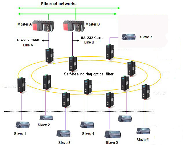
RS-232 Self-healing Ring Fiber Optic Converter
HFD-FO-232 Self-healing Ring(DSHR) Multi-drop Bus Fiber Optic Converter
The RS-232 Dual Self-healing Ring Transmission series products provide an optical self-healing ring network for RS232 data interfaces over two multi mode or single mode optical fibers. The system offers maximum reliability as it can recover simultaneous faults or failures in two different locations and has contact closure outputs on each module to clearly indicate any fault location. The self-healing ring consists of two opposing data paths, ring A and ring B. Under normal operation only the primary path (ring A) is used for data transfer. If a fault is detected, the data is transferred to the secondary path (ring B) without interruption to the communications network.
The series is available in wall mount, DIN rail or 3U chassis card.
Product Features
Supports RS232 data, Dual redundant power supply
Multimode and singlemode solutions
Contact closure alarm outputs per station
Single or dual fibre configurations
DIN rail and 3U chassis card
Typical Topology:
Specifications:
| Data | |
| Data Formats | RS232 |
| RS232 Data Rate | 115.2kbps |
| RS422 / 485 Data Rate | 512 kbps or 1Mbps |
| Bit Error Rate | <1 x 10-12 |
| Connectors | |
| Data | DB9 Female Connector |
| Fiber | ST, SC or FC (ST fitted as standard) |
| Environmental | |
| Operating Temperat ure | - 3 0 C--- +70 C |
| Storage Temperature | - 3 0 C--- +70 C |
| Operating Humidity | 0- 95% |
| MTBF | >100,000 Hours |
| Optical | |
| Fiber | Multi mode or single mode |
| Wavelength | MM: 850nm, SM: 1310nm |
| Number of fibers | 4 or 2 |
| POWER | |
| Power Input | AC 220V 110v or DC+110V +5V +12V +24V +48V Option |
| Mechanical | |
| Dimensions | DIN Rail 43*88.5*124.5mm(W*D*H) |
Ordering Information:
|
Model Number |
Description |
Fiber No. |
Fiber Mode |
Fiber Connector |
|
HFD-FO-232-R2M |
Redundant Ring Link,Dual Fiber(BI-DI), 2km |
2 |
Multi Mode |
ST/SC/FC |
|
HFD-FO-232-R4M |
Redundant Ring Link,4 Fiber, 2km |
4 |
Multi Mode |
ST/SC/FC |
|
HFD-FO-232-R2S |
Redundant Ring,Dual Fiber(BI-DI), 20km |
2 |
Single Mode |
ST/SC/FC |
|
HFD-FO-232-R4S |
Redundant Ring,4 Fiber, 20km |
4 |
Single Mode |
ST/SC/FC |
RS-232 Multi Drop Bus Fiber Optic Converter

DIN Rail RS-232 Fiber Optic Modem(Multi-drop Bus Link)
The DIN Rail RS- 232 Multi-Drop Bus Fiber Optic Modem series products provide an optical bus network for RS-232 data interfaces over a pair of multi mode or single mode optical fibers. The Terminal module units operate as the end or terminal points and provide an electrical connection and a two fibre optical connection. The Repeater module units act as in-line repeater stations and provide a single electrical connection and two optical connections, one upstream and one downstream. This series is available in either wall mount, DIN rail or 3U chassis card configurations.
Product Features
Multi protocol data interface
Switchable termination and biasing
Multimode and singlemode
Wall mount, DIN and 3U chassis card
Specs:
| Data | |
| Data Formats | RS232,RS422,RS485 |
| RS232 Data Rate | 115.2kbps |
| RS422 / 485 Data Rate | 512 kbps or 1Mbps |
| Bit Error Rate | <1 x 10-12 |
| Connectors | |
| Data | DB9 Female Connector |
| Fiber | ST, SC or FC (ST fitted as standard) |
| Environmental | |
| Operating Temperat ure | - 3 0 C--- +70 C |
| Storage Temperature | - 40 C--- +85 C |
| Operating Humidity | 0- 95% |
| MTBF | >100,000 Hours |
| Optical | |
| Fiber | Multi mode or single mode |
| Wavelength | MM: 850nm, SM: 1310nm |
| Number of fibers | 4 or 2 |
| POWER | |
| Power Input | AC 220V 110v or DC+110V +5V +12V +24V +48V Option,Dual power supply |
| Mechanical | |
| Dimensions | DIN Rail 43*88.5*124.5mm(W*D*H) |
Ordering Information:
|
Model Number |
Description |
Fiber No. |
Fiber Mode |
Fiber Connector |
|
HFD-FO-232-M2M |
Multi Drop Bus Link,Dual Fiber(BI-DI), 2km |
2 |
Multi Mode |
ST/SC/FC |
|
HFD-FO-232-M4M |
Multi Drop Bus Link,4 Fiber, 2km |
4 |
Multi Mode |
ST/SC/FC |
|
HFD-FO-232-M2S |
Multi Drop Bus Link,Dual Fiber(BI-DI), 20km |
2 |
Single Mode |
ST/SC/FC |
|
HFD-FO-232-M4S |
Multi Drop Bus Link,4 Fiber, 20km |
4 |
Single Mode |
ST/SC/FC |
RS-232 Fiber Optic Converter(Point to Point)
DIN Rail RS-232 Fiber Optic Converter
The RS-232 data series uses the most advanced digital technologies to provide excellent repeatable performance for today's data systems. It supports transmission of one bi-directional data channel over one multi mode or single mode optical fiber. RS232 standards are fully supported. The plug-and-play design ensures ease of installation with no electrical or optical adjustment needed. LED indicators are provided to show the operational status of the unit clearly.The series is available in DIN Rail compact wall mount or 3U chassis card.
The RS-232 Series fiber optic converter is equipped with a multiple interface circuit that can handle RS-232 serial interfaces and multi-mode or single- mode fiber. RS-232 converters are used to extend serial transmission distance up to 2 km (multi-mode fiber) or up to 20-100km (single- mode fiber)...Auto Baud Rate DetectionThe RS-232 Series incorporates a method for automatically detecting the serial signal baud rate by hardware. This is an extremely convenient feature for the user. Even if a device's baud rate is changed, the signal will still be transmitted through the RS-232 to fiber converter without any problem.
Product Features:
Supports RS232, Dual redundant power supply
Multimode and singlemode solutions
Switchable 120Ω Termination and biasing
LED indicators provide quick diagnosis of all important system parameters
Up to 14 units in a 3U chassis
Compact and 3U chassis card configuration
Specs:
| Data | |
| Data Formats | RS232 |
| RS232 Data Rate | 115.2kbps |
| RS422 / 485 Data Rate | 512 kbps or 1Mbps |
| Bit Error Rate | <1 x 10-12 |
| Connectors | |
| Data | DB9 Female Connector |
| Fiber | ST, SC or FC (ST fitted as standard) |
| Environmental | |
| Operating Temperat ure | - 3 0 C--- +70 C |
| Storage Temperature | - 40 C--- +85 C |
| Operating Humidity | 0- 95% |
| MTBF | >100,000 Hours |
| Optical | |
| Fiber | Multi mode or single mode |
| Wavelength | MM: 850nm, SM: 1310nm |
| Number of fibers | 1 or 2 |
| POWER | |
| Power Input | AC 220V 110v or DC+110V , +5V , +12V , +24V , +48V Option |
| Mechanical | |
| Dimensions | DIN Rail 43*88.5*124.5mm(W*D*H) |
Ordering Information:
|
Model Number |
Description |
Fiber No. |
Fiber Mode |
Fiber Connector |
|
HFD-FO-232-P1M |
Point to point Link,Single Fiber(BI-DI), 2km |
1 |
Multi Mode |
ST/SC/FC |
|
HFD-FO-232-P2M |
Point to point Link,Dual Fiber, 2km |
2 |
Multi Mode |
ST/SC/FC |
|
HFD-FO-232-P1S |
Point to point Link,Single Fiber(BI-DI), 20km |
1 |
Single Mode |
ST/SC/FC |
|
HFD-FO-232-P2S |
Point to point Link,Dual Fiber, 20km |
2 |
Single Mode |
ST/SC/FC |