Sidebar
News Press

Administrator
Our Canbus Fiber Optic Modems Mounted in Turkish Fire Alarm System
In November,our Canbus Fiber Optic modems were mounted to a fire alarm system in Turkey,the integrator is Honey well and we are the product supplier.
Our RS-485 Self-healing Ring Fiber Optic Converters Used in Qatar Chemical Factory

Datasheet of our GPS NTP Time Server
What's Fiber Media Converter?
Fiber media converter
Fiber media converters are simple networking devices that make it possible to connect two dissimilar media types such as twisted pair with fiber optic cabling. They were introduced to the industry nearly two decades ago[when?], and are important in interconnecting fiber optic cabling-based systems with existing copper-based, structured cabling systems. They are also used in MAN access and data transport services to enterprise customers.
Media conversion types
Fiber media converters support many different data communication protocols including Ethernet, Fast Ethernet, Gigabit Ethernet, T1/E1/J1, DS3/E3, as well as multiple cabling types such as coax, twisted pair, multi-mode and single-mode fiber optics. Media converter types range from small standalone devices and PC card converters to high port-density chassis systems that offer many advanced features for network management.
On some devices, Simple Network Management Protocol (SNMP) enables proactive management of link status, monitoring chassis environmental statistics and sending traps to network managers in the event of a fiber break or even link loss on the copper port.
Fiber media converters can connect different Local area network (LAN) media, modifying duplex and speed settings. Switching media converters can connect legacy 10BASE-T network segments to more recent 100BASE-TX or 100BASE-FX Fast Ethernet infrastructure. For example, existing Half-Duplex hubs can be connected to 100BASE-TX Fast Ethernet network segments over 100BASE-FX fiber.
When expanding the reach of the LAN to span multiple locations, media converters are useful in connecting multiple LANs to form one large campus area network that spans over a limited geographic area. As premises networks are primarily copper-based, media converters can extend the reach of the LAN over single-mode fiber up to 130 kilometers with 1550 nm optics.
Wavelength-division multiplexing (WDM) technology in the LAN is especially beneficial in situations where fiber is in limited supply or expensive to provision. As well as conventional dual strand fiber converters, with separate receive and transmit ports, there are also single strand fiber converters, which can extend full-duplex data transmission up to 70 kilometers over one optical fiber.
Other benefits of media conversion include providing a gradual migration path from copper to fiber. Fiber connections can reduce electromagnetic interference.
Also fiber media converters pose as a cheap solution for those who want to buy switches for use with fiber but do not have the funds to afford them, they can buy ordinary switches and use fiber media converters to use with their fiber network.
Our Profibus Self-healing Ring OLM Applied in Mid-east Airport

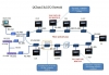
Our Ethernet Switches Used in ABB(China)'s Steel Plant Projects
Project Overview
With the rapid development of the national economy and the state of the strong commitment of the infrastructure, China's surge in demand for steel, the steel mills to increase productivity and steel quality, the general DCS control system to replace the conventional analog control. DCS control system, via Industrial Ethernet in different plant instrumentation and PLC connected to the same network, and remote monitoring.
ABB has the steel and nonferrous metals industry-leading automation solutions provider, established long-term cooperation relationship with many steel makers in China. Automated reconstruction projects in several major steel mills in Henan, one of the main providers of industrial Ethernet switch and serial communication products together to provide customers with the perfect solution.
In Steel DCS,they used BUENO's industrial ethernet switches products, including HFB5, HFB5-SC, HFB8M-2SC and HFB24-2SC and other solution features include:
By RingOn function ring network self-healing time is less than 15ms, so as to ensure real-time and reliability of the network;
Each workshop fiber connectivity, support for long distance transmission, strong anti-EMC / EMI capacity;
IP30 degree of protection, industrial DIN rail installation, to meet the steel harsh environmental requirements;
Support user-defined alarms, and via Email sent, providing the operator real-time alerts;
WEB-based management approach, to facilitate the system for remote maintenance and management.
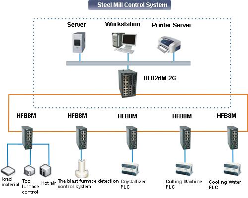
GPS NTP Time Server
GPS NTP Time Server(GPS Time Synchronized Clock)
Product descriptions:
The SY series of GPS Standard Time Synchoronous Clock that we manufactured are specifically for power system, automatizatio system, communicate system and traffic system that need high-precise time requirer.Our system is based on GPS, and the precision of time is 1µs.The facility is secondary developed with the GPS receiver that made by the special factory of United States. It can track 12 GPS satellites at the same time, and selects the best satellite automaticly for locating and timing.It outputs 1PPS, 1PPM, 1PPH time pulse and UTC time ,and the synchronous precision is 1µs, and it can measure the industrial frequency, and outputs date, time, cycle clock, cycle, clock difference, safe running days, and so on through RS232 serial with two formats. It is selected to used by automatization facilities that need standard time in electric power system.
Technical parameter:
1. Receiving frequency:1575.42MHZ, it can track 8-12 GPS satellites at the same time.
2. Antenna radio sentivity:-166dbw, with 30 metres wire. If the wire is not long enough, customer can prolong it by himself by selection of coaxial-cable that attenuation of
1.56GHZ is not more than 0.7db per metre, the attenuation of prolonged cable is not more than
5db.
3. Capture time: from 20 seconds to 2 minutes
(Annotate: the outputs of synchronous clock are all isolated by photoelectricity coupling and output 60ns)
4.1PPS output:
Timing varacity: 1µs Voltage: TTL voltage Polarity: positive pulse Pulse width: about 100ms Impedence: 50 Ώ Channel number: 1
Fore edge: <20ns
5.1PPM: output:
Timing varacity:: 1µs Voltage: TTL
Polarity: positive pulse Pulse width: about 100ms
Impedence: 50 Ώ Fore edge: <20ns
6.1PPH output:
Timing varacity:: 1µs Voltage: TTL
Polarity: positive pulse Pulse width: about 100ms
Impedence: 50 Ώ Fore edge: <20ns
7.Cycle precision: ±0.001
8.Industry frequency clock: the clock that is promoted by industry electricity is synchronous with standard clock when power is on.
9.Clock difference: that is standard clock minus industry frequency clock,synchronous time difference is zero,precision is 20 ms.
10.Longitude, latitude: where the electric power synchronous clock locates.
11.Display: 14 bits LCD display that includes cycle,date,time,longitude,latitude,industry frequency clock,clock difference (standard clock minus industry frequency clock).
12.RS232: output time code (year, month, day, hour, minute, second), industry frequency clock time(hour, minute, second), clock difference,cycle.
13.RS232: output “ST” format time code (selected by switching circuitry)
14.Power: AC110V to 240V or DC12V to 48V, 10%, 15W.
15.Size: standard industry 19 inch 2U box.1U and 3U can also be provided.
16. OEM is accepted.
Product features and advantages:
1.SY GPS NTP time server supports GPS or BD satellite systems.
2.SY GPS NTP time server incudes master clock, 30m long GPS antenna,software and mount brackets.
3.NTP/SNTP,RS485/232 and Irig-B output ports can be extended according to customer's requests.Both GPS time server and power supply can made to be redundant.
4.Antenna,mount kits and software are all free.
5.Silver or black color 1U,2U or 3U chassis
6.Low cost & 5 years warranty
7.Application: Electrical Substation, ITS,etc.
Ordering information:
|
Model |
Technical Parameters
|
Comment (Optional dual power) |
|
SY-GPS-2-G |
2 channel 1 PPS,2 channel 1 PPM , 1 channel 1 PPH (TTL/ active optical isolation and passive) 4 channel RS232, 2 channel RS485 (serial code) 2 "RS485 (IRIG-B (DC) difference), lose electric/out-of-step alarm to the 2 With expand output interface (can direct drive extension device)
|
Ac/dc power supply terminals wide input Optional NTP and optical output
|
|
SY-GPS-2-E16 |
2 channel 1 PPS,2 channel 1 PPM , 1 channel 1 PPH (TTL/ active optical isolation and passive) 4 channel RS232, 2 channel RS485 (serial code) 16channel"RS485 (IRIG-B (DC) difference), lose electric/out-of-step alarm to the 2 With expand output interface (can direct drive extension device)
|
Ac/dc power supply terminals wide input Optional NTP and optical output
|
|
SY-2U-TIME SY-2U-GPS-CPU X1 SY-2EX-IRIG-B(DC) X1 |
12 "RS485 (IRIG-B (DC) difference), lose electric/out-of-step alarm to the 2
|
2Uchassis Can be expanded plug-in |
|
SY-GPS-2-E32 |
2 channel 1 PPS,2 channel 1 PPM , 1 channel 1 PPH (TTL/ active optical isolation and passive) 4 channel RS232, 2 channel RS485 (serial code) 32 "RS485 (IRIG-B (DC) difference), lose electric/out-of-step alarm to the 2 With expand output interface (can direct drive extension device)
|
Ac/dc power supply terminals wide input Optional NTP and optical output
|
|
SY-2U-TIME SY-2U-GPS-CPU X1 SY-2EX-IRIG-B(DC) X3 |
32channel"RS485 (IRIG-B (DC) difference), lose electric/out-of-step alarm to the 2 |
2U chassis Can be expanded plug-in |
|
SY-GPS-2-FS16 (PPS OutPut) |
2 channel 1 PPS,2 channel 1 PPM , 1 channel 1 PPH (TTL/ active optical isolation and passive) 4 channel RS232, 2 channel RS485 (serial code) 2 "RS485 (IRIG-B (DC) difference), 16 channel 1 PPS / 1 PPM high-pressure high-speed photoelectric isolated active and passive output lose electric/out-of-step alarm to the 2 With expand output interface (can direct drive extension device) |
Ac/dc power supply terminals wide input Optional NTP and optical output
|
|
SY-GPS-2-FM16 (PPM ,Pulse Per Minute Output) |
|
|
|
SY-2U-TIME SY-2U-GPS-CPU X1 SY-2EX-1PPS/1PPM X1 |
12 "RS485 (IRIG-B (DC) difference), , lose electric/out-of-step alarm to the 2
|
2U chassis
|
|
SY-GPS-2-FS32(PPS Output) |
2 channel 1 PPS,2 channel 1 PPM , 1 channel 1 PPH (TTL/ active optical isolation and passive) 4 channel RS232, 2 channel RS485 (serial code) 2 "RS485 (IRIG-B (DC) difference), 32 channel 1 PPS / 1 PPM high-pressure high-speed photoelectric isolated active and passive output lose electric/out-of-step alarm to the 2 With expand output interface (can direct drive extension device) |
Ac/dc power supply terminals wide input Optional NTP and optical output
|
|
SY-GPS-2-FM32 (PPM ,Pulse Per Minute Output)) |
|
|
|
SY-2U-TIME SY-2U-GPS-CPU X1 SY-2EX-1PPS/1PPM X3 |
36 "RS485 (IRIG-B (DC) difference), , lose electric/out-of-step alarm to the 2
|
2U chassis |
|
SY-GPS-2-NET |
2 channel 1 PPS,2 channel 1 PPM , 1 channel 1 PPH (TTL/ active optical isolation and passive) 4 channel RS232, 2 channel RS485 (serial code) 2 "RS485 (IRIG-B (DC) difference), lose electric/out-of-step alarm to the 2 With expand output interface (can direct drive extension device) 2 "NTP/TCP network time output
|
Ac/dc power supply terminals wide input. Optional fiber optical output
|
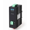
CAN Bus Fiber Optic Converter
CAN Bus to Fiber optic Converter(No Cascading/High rate & Far distance)
Product Description:
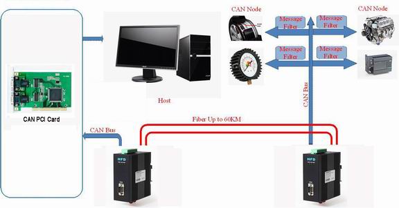
The HFD-FO-CAN CAN bus to Fiber Converter support all the transmission speeds (transmission rates):0-1Mbps.The transmission rate is set automatically as soon as the canbus HFD-FO-CAN receives a frame. The setting or adjustment is dependent on the transmission rate. The HFD-FO-CAN CAN FO converter is developed out based on the growing market demand for CAN Bus long distance transmission without any cascading(attenuation).The HFD-FO-CAN uses the most advanced new technology in the world,which is the foundation of the high rate transmission(1MB) over more than 20km without any cascading or delay.Thanks to the advanced technology and high performance,the HFD-FO-CAN to Fiber Converter can be applied in very important projects and harsh places.
Segment monitoring at the optical line:
Each receiver monitors the optical line port connected to it for receive frames and status. If faulty frames are received by the receiver, or no single for longer than the maximum permitted time, forwarding of the received signals is blocked until the port status is OK,frames can be received again correctly.The converter can be equipped with buffering elimination function after 300ms or when the buffer is full.
Network Topologies:
The following network topologies can be realized with the HFD-FO-CAN:
- Point-to-point topologies
- Multi-drop Bus
Fiber Mode: Single mode or Multi Mode
Product Feature & Benefits:
- Buffer function:The HFD-FO-CAN CAN Bus Fiber Optic Converter can protect the data from being lost.The isolation inside the HFD can ensure the converters work normally under harsh environments.Anti-stream function,Buffering: 1000 frames.
- No cascading: The HFD-FO-CAN has no cascading,no frame loss when data is at high rate or long distance transmission.
- Reliability: Compared with other brands,the HFD-FO-CAN can help build up more stable and secure networks,it can maximumly reach 6500 frames/S.
- Buffer clearance: Clear the buffer in nominated time(For Option)
- High rate: Up to 1Mbps(20km distance simultaneously)
Application:
Fire control panel, radar system, security, battery system, film, automative industry, power SCADA, Elevator, industrial automation, solar plant, Wind farm and other industrial fields.
Other Specs:
|
Technical Data |
|
|
Voltage/power supply |
9 to 30V DC |
|
Operating voltage |
9 V to 30 V DC, typ. 24 V, |
|
Current consumption |
typ. 80 mA@24V |
|
Output voltage/current (Pin 6 Sub-D socket) |
5 V +5%,–10%/ 90 mA |
|
Signaling contact Signal transmission |
Max .switch DC24V@2A or This email address is being protected from spambots. You need JavaScript enabled to view it. |
|
Transmission rate |
0-1Mbps |
|
Setting transmission rate |
Rotary button or software |
|
Bit error rate |
< 10-9 |
|
Electrical port |
Terminal or DB9 |
|
Input/output signal |
CAN2.0A, CAN2.0B,ISO-11898 |
|
PIN assignment |
|
|
Optical ports |
1 or 2 (2 as standard) |
|
Wavelength |
SM:1310/1550nm, MM:850/1310nm |
|
optical power:– in glass fiber 9/125um – in glass fiber G 62.5/125 |
-9dBm – -18 dBm -13 dBm – -20 dBm |
|
Receiver sensitivity |
-34dBm |
|
Transmission distance:with glass fiber 9/125um with glass fiber G 62,5/125 |
0 – 20,000 m (0.3 dB/km) 0 – 3,000 m (2.0 dB/km) |
|
Connector |
ST/FC/SC |
|
Others |
|
|
Ambient temperature |
-30 °C to +70 °C |
|
Storage temperature |
–40 °C to +85 °C |
|
Relative humidity |
<95 %, non-condensing |
|
Protection class |
IP 30 |
|
Dimensions (W x H x D) |
43 x 88.5 x 124.5mm(W*D*H) |
|
Housing material/Color |
Die-cast zinc/Black |
|
Weight |
approx. 600 g |
Electromagnetic compatibility (EMC)
Limit class B (EN 55022)
EN 61000-4-2
EN 61000-4-3)
Burst: On power supply lines and shielded RS 485 bus lines: ±2 kV (EN 61000-4-4)
Surge: Power lines: ±1 kV symmetrical,Shielded RS 485 lines: ±2 kV asymmetrical (EN 61000-4-5)
Ordering Information:
|
Model Number |
Description |
Fiber No. |
Fiber Mode |
Fiber Connector |
|
HFD-FO-CAN-P1M |
Point to point Link,Single Fiber(BI-DI), 2km |
1 |
Multi Mode |
ST/SC/FC |
|
HFD-FO-CAN-P2M |
Point to point Link,Dual Fiber, 2km |
2 |
Multi Mode |
ST/SC/FC |
|
HFD-FO-CAN-P1S |
Point to point Link,Single Fiber(BI-DI), 20km |
1 |
Single Mode |
ST/SC/FC |
|
HFD-FO-CAN-P2S |
Point to point Link,Dual Fiber, 20km |
2 |
Single Mode |
ST/SC/FC |
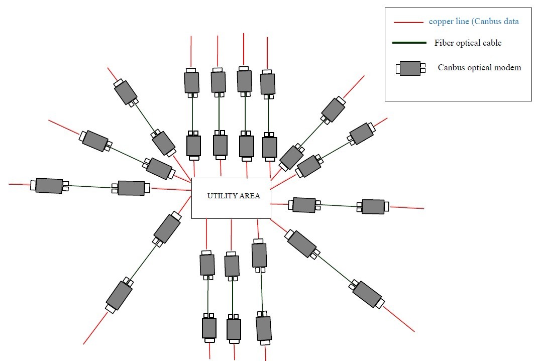
CAN Bus Multi-drop BUS Fiber Optic Converter
Intelligent Multi-drop CAN BUS Fiber Media Converter
Transmission rate:
The HFD-FO-CAN support all the transmission speeds (transmission rates):0-1Mbps.The CAN BUS rate is configurable by software,it adopts the new technology,the unique feature of it is it can support complex and long networks,even when it's at 1MB(6500 frames),it can transmit 20km distance.The transmission rate is set automatically as soon as the HFD-FO-CAN receives a frame. The setting or adjustment is dependent on the transmission rate. Depending on the HFD-FO-CAN Settings in automatical mode,Segment monitoring at the optical line.Each receiver monitors the optical line port connected to it for receve frames and status. If faulty frames are received by the receiver, or no single for longer than the maximum permitted time, forwarding of the received signals is blocked until the port status is ok,frames can be received again correctly.
Feature:
-
Long distance transmision
-
High frames: 6500 frames/second
-
Anti-stream: 1000 frames buffering
-
Can be used in complex and harsh networks

Network Topology: Multi-drop Bus
|
Technical Data |
|
|
Voltage/power supply |
5V/12V/24V DC,Dual Power Supply |
|
Operating voltage |
9 V to 30 V DC, typ. 24 V, |
|
Current consumption |
typ. 80 mA@24V |
|
Output voltage/current (Pin 6 Sub-D socket) |
5 V +5%,–10%/ 90 mA |
|
Signaling contact Signal transmission |
Max .switch DC24V@2A or This email address is being protected from spambots. You need JavaScript enabled to view it. |
|
Transmission rate |
0-1Mbps |
|
Setting transmission rate |
Automatic or Switch setting |
|
Bit error rate |
< 10-9 |
|
Electrical port |
Terminal or DB9 |
|
Input/output signal |
CAN2.0A, CAN2.0B,ISO-11898 |
|
PIN assignment |
|
|
Optical ports |
2 or 4 (4 as standard) |
|
Wavelength |
SM:1310nm, MM:850nm |
|
optical power:– in glass fiber 9/125um – in glass fiber G 62.5/125 |
-9dBm – -18 dBm -13 dBm – -20 dBm |
|
Receiver sensitivity |
-34dBm |
|
Transmission distance:with glass fiber 9/125um with glass fiber G 62,5/125 |
0 – 20,000 m (0.3 dB/km) 0 – 3,000 m (2.0 dB/km) |
|
Connector |
ST/FC/SC |
|
Others |
|
|
Ambient temperature |
-30 °C to +70 °C |
|
Storage temperature |
–40 °C to +85 °C |
|
Relative humidity |
<95 %, non-condensing |
|
Protection class |
IP 30 |
|
Dimensions (W x H x D) |
43(W) x 88.5(D) x 124.5(H) mm |
|
Housing material/Color |
Die-cast zinc/Black |
|
Weight |
approx. 650 g |
Electromagnetic compatibility (EMC)
Limit class B (EN 55022)
EN 61000-4-2
EN 61000-4-3)
Burst: On power supply lines and shielded RS 485 bus lines: ±2 kV (EN 61000-4-4)
Surge: Power lines: ±1 kV symmetrical,Shielded RS 485 lines: ±2 kV asymmetrical (EN 61000-4-5)
Application: The HFD-FO-CAN converter can be used in fire alarm system,radar system,security,industrial automation,solar plant and other industrial fields.
Ordering Information:
|
Model Number |
Description |
Fiber No. |
Fiber Mode |
Fiber Connector |
|
HFD-FO-CAN-M2M |
Multi Drop Bus Link,Dual Fiber(BI-DI), 2km |
2 |
Multi Mode |
ST/SC/FC |
|
HFD-FO-CAN-M4M |
Multi Drop Bus Link,4 Fiber, 2km |
4 |
Multi Mode |
ST/SC/FC |
|
HFD-FO-CAN-M2S |
Multi Drop Bus Link,Dual Fiber(BI-DI), 20km |
2 |
Single Mode |
ST/SC/FC |
|
HFD-FO-CAN-M4S |
Multi Drop Bus Link,4 Fiber, 20km |
4 |
Single Mode |
ST/SC/FC |
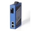
Gigabit Ethernet Industrial Media Converter
|
OPTICAL |
|
|
Number of Fibers |
2 or 1 |
|
Wavelength |
SM:1310/1550nm, MM:850/1310nm |
|
Fiber Type |
9/125μ m(SM).62.5/125um(MM) |
|
Distance |
0 ~ 20km(SM), 0~2km(MM) |
|
Connector Type |
ST/FC/SC |
|
GENERAL |
|
|
Operating Temperature |
-40 ~ 70C / -40 ~ +158F |
|
Relative Humidity |
0 ~ 95% non-condensing |
|
Mean Time Between Failure (MTBF) |
> 600, 000hrs |
|
Power Supply Adaptors |
AC 220V 110v or DC+110V, +5V, +12V, +24V, +48V Option |
|
Enclosure Color |
Blue |
|
Dimensions ( H× W× D ) |
120× 40× 92mm DIN Rail |
Ordering Information:
|
Model Number |
Description |
Fiber No. |
Fiber Mode |
Fiber Connector |
|
HFD-FO-1000M-P1M |
Point to point Link,Single Fiber(BI-DI), 2km |
1 |
Multi Mode |
ST/SC/FC |
|
HFD-FO-1000M-P2M |
Point to point Link,Dual Fiber, 2km |
2 |
Multi Mode |
ST/SC/FC |
|
HFD-FO-1000M-P1S |
Point to point Link,Single Fiber(BI-DI), 20km |
1 |
Single Mode |
ST/SC/FC |
|
HFD-FO-1000M-P2S |
Point to point Link,Dual Fiber, 20km |
2 |
Single Mode |
ST/SC/FC |