Sidebar
News Press

Administrator
CAN to Fiber Optic Converter
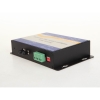
CAN to Fiber Converter(New Technology)
The CAN Bus series products provide an optical point-to-point or bus network connection for CAN bus data interfaces on one or two, multi mode or single mode optical fibers. The CAN Bus Point-to-Point Transmission units operate as the end or terminal points and provide an electrical connection and a two fiber optical connection. The units support CAN 1.0 and CAN 2.0 CAN standards, and Device Net. And are transparent to all high level protocols.This series is available in either wall mount, DIN rail or 3U chassis card configurations.
Product Features
- Up to 1Mbps data rate(Support high rate and long distance transmission)
- Baud rate Configurable
- Multimode and singlemode
- Anti-stream: 1000 frames buffering
- Single fiber solution
- Wall mount, rack or chassis configurations
| Data | |
| Data Formats | CAN1.0 ,CAN2.0 , Device Net |
| CAN Data Rate | 0-1Mbps |
| Bit Error Rate | <1 x 10-12 |
| Connectors | |
| Data | Screw Block Terminal |
| Fiber | ST, SC or FC (ST fitted as standard) |
| Environmental | |
| Operating Temperat ure | - 3 0 C--- +70 C |
| Storage Temperature | - 40 C--- +85 C |
| Operating Humidity | 0- 95% |
| MTBF | >100,000 Hours |
| Optical | |
| Fiber | Multimode or singlemode |
| Wavelength | MM: 850nm, SM: 1310nm |
| Number of fibers | 2 or 1 |
| POWER | |
| Power Input | +9 to +40V DC |
| Mechanical | |
| Dimensions | 156(W)×108(D)×33.6(H )mm Wall Mount & DIN Rail |
|
Model Number |
Description |
Port No. |
Fiber Mode |
Fiber Connector |
|
HFD-FO-CAN-P1M |
Fiber Optic Converter,Point to Point Link, Single Fiber(BI-DI), 2km,DIN Rail Mount |
1 CAN +1 FO |
Multi Mode |
ST/SC/FC |
|
HFD-FO-CAN-P2M |
Fiber Optic Converter,Point to Point Link, Dual Fiber, 2km,DIN Rail Mount |
1 CAN+1TX+1RX |
Multi Mode |
ST/SC/FC |
|
HFD-FO-CAN-P1S |
Fiber Optic Converter,Point to Point Link, Single Fiber(BI-DI), 20km |
1 CAN +1 FO |
Single Mode |
ST/SC/FC |
|
HFD-FO-CAN-P2S |
Fiber Optic Converter,Point to Point Link, Dual Fiber, 20km |
1 CAN+1TX+1RX |
Single Mode |
ST/SC/FC |
|
HFD-FO-CAN-M2M |
Fiber Optic Converter,Multi-drop Link, Dual Fiber(BI-DI), 2km |
1 CAN+2 FO |
Multi Mode |
ST/SC/FC |
|
HFD-FO-CAN-M4M |
Fiber Optic Converter,Multi-drop Link, 4 Fiber, 2km |
1 CAN+2TX+2RX |
Multi Mode |
ST/SC/FC |
|
HFD-FO-CAN-M2S |
Fiber Optic Converter,Multi-drop Link, Dual Fiber(BI-DI), 20km |
1 CAN+2 FO |
Single Mode |
ST/SC/FC |
|
HFD-FO-CAN-M4S |
Fiber Optic Converter,Multi-drop Link, 4 Fiber, 20km |
1 CAN+2TX+2RX |
Single Mode |
ST/SC/FC |
|
FO-FIB-100PT |
Configurable Fiber Optic Converter, Point to Point Link,Wall Mount |
1CAN+1TX+1RX |
Single Mode |
ST/SC/FC |
|
FO-FIB-100BT |
Configurable Fiber Optic Converter, Multi Drop Link,Wall Mount |
1CAN+2TX+2RX |
Single Mode |
ST/SC/FC |
|
FO-FIB-MIXED |
Configurable CAN Fiber Optic Switch, Point to point,Multi-drop,Star,Tree, Wall Mount |
2 CAN+ FO(2TX+2RX) |
Single Mode |
ST/SC/FC |
|
SW-400T |
4 Port Configurable CAN BUS Switch, Wall Mount |
4 CAN |
|
|
|
BRIGE-200T |
Configurable CAN TO CAN Bridge |
2 CAN |
|
|
|
CANET-I |
1 Port CAN to Ethernet Converter |
1 CAN+1 TCP |
|
|
|
CANET-II |
2 Port CAN to Ethernet Converter |
2 CAN+1 TCP |
|
|
|
CAN-USB-I |
1 Port CAN to USB Converter |
1 CAN+1 USB |
|
|
|
CAN-USB-II |
2 Port CAN to USB Converter |
2 CAN+1 USB |
|
|
|
CAN-PCI-5001 |
1 Port CAN PCI Card |
1 CAN+1 PCI |
|
|
|
CAN-PCI-5002 |
2 Port CAN PCI Card |
2 CAN+1 PCI |
|
|
|
CAN-232 |
CAN to RS-232 Converter |
1 CAN+1RS232 |
|
|
|
CAN-485 |
CAN to RS-485 Converter |
1 CAN+1RS485 |
|
|
Application of Profibus Fiber Optic
Profibus Fiber Optic Application in Topology
Field busses are industrial control systems using Programmable Logic Controllers (PLC) to control and manage field devices found in industrial environments. The communication medium can be any combination of copper wire,
fiber optics or wireless.
Over time, many field bus systems have been developed and several are standardized in IEC 61158. IEC 61158 describes PROFIBUS as Type 3 and PROFInet as Type 10. IEC 61784 further defines communication profiles and sets.
• Profile set 3/1 is used with PROFIBUS asynchronous transmission using RS485 in the physical layer.
• Profile set 3/2 is used with PROFIBUS synchronous transmission using Manchester encoding while distributing Bus Power (MBP).
• Profile set 3/3 is used with PROFInet using TCP/IP Ethernet.
Benefits of PROFIBUS include:
• Cost savings due to fewer bus components and easier installation.
• Easier management due to improved asset management tools.
• Improved productivity and reduced down time due to manufacturing flexibility
PROFIBUS (PROcess FIeld BUS) has two versions: PROFIBUS DP (Decentralized Periphery) and PROFIBUS PA. PROFIBUS DP is used in production and automation and makes up about 90% of the PROFIBUS field devices. PROFIBUS PA is used in applications needing power distribution to the devices and where intrinsically safe operation may be required.
PROFIBUS DP is bit-serial asynchronous communication using non-return to zero (NRZ) encoding running at bite rates from 9.6kbps to 12Mbps.
The PROFIBUS DP copper wire medium is balanced twisted pair transmission line according to ANSI TIA/EIA-
485-A forming a bus between the PLC and up to 31 field devices. Using shielded twisted pair is recommended and end terminations are required. In a linear topology, the number of field devices may be increased to 122 by adding a maximum of three repeaters. The interface is a 9-pin sub-D connector.
The PROFIBUS DP fiber optic medium can be either plastic or glass fiber using BFOC/2.5 connectors. An optical- electrical converter translates between the fiber optic medium and copper wire medium. The fiber optic medium insensitive to electrical noise, provides metallic isolation, and can span long distances. PROFIBUS PA does not support fiber optic medium.
A two port optic repeater with single electrical RS485 port forms a T-Connector. The T-Connector can be used as a simple optical-electrical converter, as an optic repeater, or as optic repeater with RS485 add/drop operation. In the optic repeater with RS485 add/drop operation, PROFIBUS devices in a tree topology can be distributed at great distances from the PLC.
This article deals with use of fiber optics in Profibus network.
As stated above Profibus is used in large factory automation projects e.g. Auto/Truck manufacturing, cement, steel, aluminum plants, food processing, chemical plants, water and sewage treatment plants. One such example is shown in figure 1. Large plants use heavy machinery, motors, generators which generate lot of EMI/RFI (noise), which can interfere with sensitive data communication between various computers and process control equipment. Plants also use high voltage, high currents which can cause problems with datacom and control equipment. If plant is old and proper grounding is not used, ground loops can result which are serious problem to new low voltage digital circuits and data communication.
In large manufacturing plants, distances can be one kilometer to several kilometers which is beyond the data communication limits of most computers and process control equipment. All of these problems can be overcome with use of fiber optic cabling and optical equipment.
Key Advantages of Fiber
All Dielectric
• Low Signal Radiation
• Secure Transmission
• RFI and EMI Immunity
• High Voltage Installations
Small Size
• Less Duct Space
• Fewer Additional ducts Installed
Low Attenuation
• Greater Distance/Fewer Repeaters
• Less Installation and maintenance
Optical Signal
• No ground Loops
• No Spark Hazard
• Operation in Flammable Area
High Bandwidth
• Future Signal Capability Expansion
Advantages Explained
1. Secure communication (low signal radiation):
Data traveling over fiber is very secure. No electronic eves dropping can be used making it extremely difficult to “Tap” fiber optic cable. Also, if tapped it is very easy to determine that cable is tapped.
2. Immunity from EMI/RFI/High Voltage/Lightning:
Resulting in clean, error free data transmission over long distances bit error rates of better than 10-9. Fiber is made of glass or plastic all dielectric material which is not affected by proximity to high voltage or lightning. Fiber optic cable can be routed in same ducts or cable trays as high voltage or power cables. Saving cost and providing ease of installation.
3. Small Size:
Fiber optic cables are physically very small and light weight, saving space, weight, and allowing ease of installation.
4. Lightning damage:
Particularly outdoors between buildings etc. can be avoided with use of F.O cable. If lightning strikes one plant it does not travel to other parts of same plant as F.O cable provides electrical isolation.
5. No Ground Loops:
Expensive grounding and shielding not required – saving on installation cost. Also, protects equipment from high voltage damage.
6. Low Loss (low signal attenuation):
Data can be sent long distances error free. With proper F.O. equipment and cabling 100 Km is possible without repeaters.
7. High data rate and High bandwidth:
Large data files such as engineering drawings can be transmitted in seconds. This allows main computers or process controllers to be in a more controlled and safe area away from plant. Also, future proofs installation.
8. No Spark Hazard:
Extremely important in chemical plants, oil refineries and other hazardous locations, since fiber cable is made of glass or plastic, if cut no electrical sparks. This way cable cut cannot start a fire.
To take advantage of fiber optic cabling and associated benefits, we have to use appropriate fiber optic equipment. In case of large plants, many use “Profibus” and “Profinet”.
HFB-DM “Profibus-DP” fiber optic bit driver is specifically developed for use in “Profibus” network. HFB-DM comes with many options such as multimode fiber, single mode fiber, plastic or glass fiber. This
allows implementation in any size, small to large plants with any of type of fiber optic cabling. RS485 (DB9) side
allows multi dropping to various pieces of equipment such as a Bar Code reader, motor controls, electronic scale, and so on allowing integration of all plant equipment into network.
Various data rates are possible from 9600 Bps to 12 Mbps. This way high and low speed equipment can be integrated on to “Profibus”.
HFB-DM is a two port fiber optic repeater so equipment can be daisy chained or connected in point to point or star configuration which allows total flexibility to plant engineers for network configuration.
HFB-DM is Din rail mountable so common rails can be used. Also the unit provides status indicators showing activity such as power ON/OFF, TXD and RXD fiber activity, and invalid switch setting for RS485.
HFB-DM was tested and approved by “Profibus Lab” an outside independent laboratory testing for compatibility with “Profibus” network and various manufacturer’s equipment and Profibus specification.
HFB-DM comes in Ruggedized highly shielded metal enclosure. Boards are conformal coated for protection from dust/sand/moisture, so that the product can be used in any part of world. Units with multimode fiber is rated
–25 to +70oC and single mode is rated –25 to +60oC.
If application requires short distance and low data rate, low cost plastic fibers and 2145-00 units can be used. HFB-DM is UL approved, is designed to meet FCC Class B, Part 15 and CE requirements.
HFB-DM uses 24VDC and 3 Watts input power.
HFB-DM is field proven with ABB advent controller AC31/AC800F/800XA. It can also be used with
Siemens, Allen Bradley GE and other process controllers.
10/100/1000 Ethenrt Fiber Media Converter with Redundant Power
Serial Converters and Serial Ports
In computing, a serial port is a serial communication physical interface through which information transfers in or out one bit at a time (in contrast to a parallel port).[1] Throughout most of the history of personal computers, data transfer through serial ports connected the computer to devices such as terminals and various peripherals.
While such interfaces as Ethernet, FireWire, and USB all send data as a serial stream, the term "serial port" usually identifies hardware more or less compliant to the RS-232 standard, intended to interface with a modem or with a similar communication device.
Modern computers without serial ports may require serial-to-USB converters to allow compatibility with RS 232 serial devices. Serial ports are still used in applications such as industrial automation systems, scientific instruments, shop till systems and some industrial and consumer products. Server computers may use a serial port as a control console for diagnostics. Network equipment (such as routers and switches) often use serial console for configuration. Serial ports are still used in these areas as they are simple, cheap and their console functions are highly standardized and widespread. A serial port requires very little supporting software from the host system.
Hardware
Some computers, such as the IBM PC, used an integrated circuit called a UART, that converted characters to (and from) asynchronous serial form, and automatically looked after the timing and framing of data. Very low-cost systems, such as some early home computers, would instead use the CPU to send the data through an output pin, using the so-called bit-banging technique. Before large-scale integration (LSI) UART integrated circuits were common, a minicomputer or microcomputer would have a serial port made of multiple small-scale integrated circuits to implement shift registers, logic gates, counters, and all the other logic for a serial port.
Early home computers often had proprietary serial ports with pinouts and voltage levels incompatible with RS-232. Inter-operation with RS-232 devices may be impossible as the serial port cannot withstand the voltage levels produced and may have other differences that "lock in" the user to products of a particular manufacturer.
Low-cost processors now allow higher-speed, but more complex, serial communication standards such as USB and FireWire to replace RS-232. These make it possible to connect devices that would not have operated feasibly over slower serial connections, such as mass storage, sound, and video devices.
Many personal computer motherboards still have at least one serial port, even if accessible only through a pin header. Small-form-factor systems and laptops may omit RS-232 connector ports to conserve space, but the electronics are still there. RS-232 has been standard for so long that the circuits needed to control a serial port became very cheap and often exist on a single chip, sometimes also with circuitry for a parallel port.
Connectors
While the RS-232 standard originally specified a 25-pin D-type connector, many designers of personal computers chose to implement only a subset of the full standard: they traded off compatibility with the standard against the use of less costly and more compact connectors (in particular the DE-9 version used by the original IBM PC-AT). The desire to supply serial interface cards with two ports required that IBM reduce the size of the connector to fit onto a single card back panel. A DE-9 connector also fits onto a card with a second DB-25 connector that was similarly changed from the original Centronics-style connector. Starting around the time of the introduction of the IBM PC-AT, serial ports were commonly built with a 9-pin connector to save cost and space. However, presence of a 9-pin D-subminiature connector is neither necessary nor sufficient to indicate use of a serial port, since this connector was also used for video, joysticks, and other purposes.
Some miniaturized electronics, particularly graphing calculators and hand-held amateur and two-way radio equipment, have serial ports using a jack plug connector, usually the smaller 2.5 or 3.5 mm connectors and use the most basic 3-wire interface.
Many models of Macintosh favored the related RS-422 standard, mostly using German Mini-DIN connectors, except in the earliest models. The Macintosh included a standard set of two ports for connection to a printer and a modem, but some PowerBook laptops had only one combined port to save space.
The standard specifies 20 different signal connections. Since most devices use only a few signals, smaller connectors can often be used. For example, the 9 pin DE-9 connector was used by most IBM-compatible PCs since the IBM PC AT, and has been standardized as TIA-574. More recently, modular connectors have been used. Most common are 8P8C connectors. Standard EIA/TIA 561 specifies a pin assignment, but the "Yost Serial Device Wiring Standard"[2] invented by Dave Yost (and popularized by the Unix System Administration Handbook) is common on Unix computers and newer devices from Cisco Systems. Many devices don't use either of these standards. 10P10C connectors can be found on some devices as well. Digital Equipment Corporation defined their own DECconnect connection system which was based on the Modified Modular Jack (MMJ) connector. This is a 6 pin modular jack where the key is offset from the center position. As with the Yost standard, DECconnect uses a symmetrical pin layout which enables the direct connection between two DTEs. Another common connector is the DH10 header connector common on motherboards and add-in cards which is usually converted via a cable to the more standard 9 pin DE-9 connector (and frequently mounted on a free slot plate or other part of the housing).
Hardware abstraction
Operating systems usually use a symbolic name to refer to the serial ports of a computer.
Unix-like operating systems usually label the serial port devices /dev/tty* (TTY is a common trademark-free abbreviation for teletype) where * represents a string identifying the terminal device; the syntax of that string depends on the operating system and the device. On Linux, 8250/16550 UART hardware serial ports are named /dev/ttyS*, USB adapters appear as /dev/ttyUSB* and various types of virtual serial ports do not necessarily have names starting with tty.
The Microsoft MS-DOS and Windows environments refer to serial ports as COM ports: COM1, COM2,..etc.
Common applications for serial ports
The RS-232 standard is used by many specialized and custom-built devices. This list includes some of the more common devices that are connected to the serial port on a PC. Some of these such as modems and serial mice are falling into disuse while others are readily available.
Serial ports are very common on most types of microcontroller, where they can be used to communicate with a PC or other serial devices.
Dial-up modems
GPS receivers (typically NMEA 0183 at 4,800 bit/s)
Bar code scanners and other point of sale devices
LED and LCD text displays
Satellite phones, low-speed satellite modems and other satellite based transceiver devices
Flat-screen (LCD and Plasma) monitors to control screen functions by external computer, other AV components or remotes
Test and measuring equipment such as digital multimeters and weighing systems
Updating Firmware on various consumer devices.
Some CNC controllers
Uninterruptible power supply
Software debuggers that run on a 2nd computer.
Industrial field buses
Historic uses
Printers
Computer terminal, teletype
Older digital cameras
Networking (Macintosh AppleTalk using RS-422 at 230.4 kbit/s)
Serial mouse
Older GSM mobile phones
Since the control signals for a serial port can be easily turned on and off by a switch, some applications used the control lines of a serial port to monitor external devices, without exchanging serial data. The most important commercial application of this principle was for some models of uninterruptible power supply which used the control lines to signal "loss of power", "battery low alarm" and other status information. At least some Morse code training software used a code key connected to the serial port, to simulate actual code use. The status bits of the serial port could be sampled very rapidly and at predictable times, making it possible for the software to decipher Morse code.
Settings
Many settings are required for serial connections used for asynchronous start-stop communication, to select speed, number of data bits per character, parity, and number of stop bits per character. In modern serial ports using a UART integrated circuit, all settings are usually software-controlled; hardware from the 1980s and earlier may require setting switches or jumpers on a circuit board. One of the simplifications made in such serial bus standards as Ethernet, FireWire, and USB is that many of those parameters have fixed values so that users can not and need not change the configuration; the speed is either fixed or automatically negotiated. Often if the settings are entered incorrectly the connection will not be dropped; however, any data sent will be received on the other end as nonsense.
Speed
Serial ports use two-level (binary) signaling, so the data rate in bits per second is equal to the symbol rate in bauds. A standard series of rates is based on multiples of the rates for electromechanical teleprinters; some serial ports allow many arbitrary rates to be selected. The port speed and device speed must match. The capability to set a bit rate does not imply that a working connection will result. Not all bit rates are possible with all serial ports. Some special-purpose protocols such as MIDI for musical instrument control, use serial data rates other than the teleprinter series. Some serial port systems can automatically detect the bit rate.
The speed includes bits for framing (stop bits, parity, etc.) and so the effective data rate is lower than the bit transmission rate. For example with 8-N-1 character framing only 80% of the bits are available for data (for every eight bits of data, two more framing bits are sent).
Common bit rates include 1200, 2400, 4800, 9600, 14400, 19200, 38400, 57600 and 115200 bit/s.[9]
Data bits
The number of data bits in each character can be 5 (for Baudot code), 6 (rarely used), 7 (for true ASCII), 8 (for any kind of data, as this matches the size of a byte), or 9 (rarely used). 8 data bits are almost universally used in newer applications. 5 or 7 bits generally only make sense with older equipment such as teleprinters.
Most serial communications designs send the data bits within each byte LSB (Least Significant Bit) first. This standard is also referred to as "little endian". Also possible, but rarely used, is "big endian" or MSB (Most Significant Bit) first serial communications. (See Endianness for more about bit ordering.) The order of bits is not usually configurable, but data can be byte-swapped only before sending.
Parity bit
Parity is a method of detecting errors in transmission. When parity is used with a serial port, an extra data bit is sent with each data character, arranged so that the number of 1 bits in each character, including the parity bit, is always odd or always even. If a byte is received with the wrong number of 1s, then it must have been corrupted. However, an even number of errors can pass the parity check.
Electromechanical teleprinters were arranged to print a special character when received data contained a parity error, to allow detection of messages damaged by line noise. A single parity bit does not allow implementation of error correction on each character, and communication protocols working over serial data links will have higher-level mechanisms to ensure data validity and request retransmission of data that has been incorrectly received.
The parity bit in each character can be set to none (N), odd (O), even (E), mark (M), or space (S). None means that no parity bit is sent at all. Mark parity means that the parity bit is always set to the mark signal condition (logical 1) and likewise space parity always sends the parity bit in the space signal condition. Aside from uncommon applications that use the 9th (parity) bit for some form of addressing or special signalling, mark or space parity is uncommon, as it adds no error detection information. Odd parity is more common than even, since it ensures that at least one state transition occurs in each character, which makes it more reliable. The most common parity setting, however, is "none", with error detection handled by a communication protocol.
Stop bits
Stop bits sent at the end of every character allow the receiving signal hardware to detect the end of a character and to resynchronise with the character stream. Electronic devices usually use one stop bit. If slow electromechanical teleprinters are used, one-and-one half or two stop bits are required.
Conventional notation
The D/P/S (Data/Parity/Stop) conventional notation specifies the framing of a serial connection. The most common usage on microcomputers is 8/N/1 (8N1). This specifies 8 data bits, no parity, 1 stop bit. In this notation, the parity bit is not included in the data bits. 7/E/1 (7E1) means that an even parity bit is added to the seven data bits for a total of eight bits between the start and stop bits. If a receiver of a 7/E/1 stream is expecting an 8/N/1 stream, half the possible bytes will be interpreted as having the high bit set.
Flow control
A serial port may use signals in the interface to pause and resume the transmission of data. For example, a slow printer might need to handshake with the serial port to indicate that data should be paused while the mechanism advances a line.
Common hardware handshake signals (hardware flow control) use the RS-232 RTS/CTS or DTR/DSR signal circuits. Generally, the RTS and CTS are turned off and on from alternate ends to control data flow, for instance when a buffer is almost full. DTR and DSR are usually on all the time and, per the RS-232 standard and its successors, are used to signal from each end that the other equipment is actually present and powered-up. However, manufacturers have over the years built many devices that implemented non-standard variations on the standard, for example, printers that use DTR as flow control.
Another method of flow control (software flow control) uses special characters such as XON/XOFF to control the flow of data. The XON/XOFF characters are sent by the receiver to the sender to control when the sender will send data, that is, these characters go in the opposite direction to the data being sent. The circuit starts in the "sending allowed" state. When the receiver's buffers approach capacity, the receiver sends the XOFF character to tell the sender to stop sending data. Later, after the receiver has emptied its buffers, it sends an XON character to tell the sender to resume transmission. These are non-printing characters and are interpreted as handshake signals by printers, terminals, and computer systems.
XON/XOFF flow control is an example of inband signaling, in which control information is sent over the same channel used for the data. If the XON and XOFF characters might appear in the data being sent, XON/XOFF handshaking presents difficulties, as receivers may interpret them as flow control. Such characters sent as part of the data stream must be encoded in an escape sequence to prevent this, and the receiving and sending software must generate and interpret these escape sequences. On the other hand, since no extra signal circuits are required, XON/XOFF flow control can be done on a 3 wire interface.
"Virtual" serial ports
A virtual serial port is an emulation of the standard serial port. This port is created by software which enable extra serial ports in an operating system without additional hardware installation (such as expansion cards, etc.). It is possible to create a large number of virtual serial ports in a PC. The only limitation is the amount of resources, such as operating memory and computing power, needed to emulate many serial ports at the same time.
Virtual serial ports emulate all hardware serial port functionality, including Baud rate, Data bits, Parity bits, Stop bits, etc. Additionally they allow controlling the data flow, emulating all signal lines (DTR/DSR/CTS/RTS/DCD/RI) and customizing pinout. Virtual serial ports are common with Bluetooth and are the standard way of receiving data from Bluetooth-equipped GPS modules.
Virtual serial port emulation can be useful in case there is a lack of available physical serial ports or they do not meet the current requirements. For instance, virtual serial ports can share data between several applications from one GPS device connected to a serial port. Another option is to communicate with any other serial devices via internet or LAN as if they are locally connected to computer (Serial-over-Ethernet technology). Two computers or applications can communicate through an emulated serial port link. Virtual serial port emulators are available for Microsoft Windows and some of them run under Windows CE, Windows Mobile and Pocket PC.
Because of the serial ports are different, so the serial converters are invented for transfering the data to different ports. Buenoptic Serial Converters are all based in industrial grade and can endure all work conditions.
Serial Device Server Passed Rohs
Buenoptic Serial Device servers and modules just passed Rohs testing, along with CE certification, our serial device server series products won good market feedback in EU market.
Worldwide Clients
China & Asia
- State Grid(SGCC)
- MEA/PEA(Th)
- NGCP(Ph)
- YPC
- SGCC NARI
- CHC
- EGAT
- PT. Kingkata Kharisma Artha
- REL Joint Venture
- Woodward India
- Eita Elevator
- ST Engineering
- Freelectron (M) Sdn Bhd
- Technocrats Security Systems Pvt. Ltd
- Larsen & Toubro Limited
- Synergy Systems & Solutions
European Union
- ABB
- Siemens Energy
- Hellenic Aerospace Industry S.A.
- Azeti Monitoring Solutions
- Merak Telecom & Systems S.L.
- Teknosis Elk.Ltd
- Ellatron d.o.o.
- CMI
- Elecnor
- Telegra d.o.o.
- Mavil Elektronik
- PearTek OY
- Toto Costruzioni
- Distrisegur Lda
- Fagor Electronica
- CETO
- EQUANS
North & South America
- Honeywell
- Trane
- AWC
- Andritz Hydro
- Federal-Mogul Corporation
- WEG
- SSS Group
- Water Systems Inc
- Traffic Fiber Systems LLC
- Ballard Power Systems
- KAP consulting
- Cameron
- Hydro Quebec
- Telcordia
- Cognizant
- Open Control Ltda
- PTI SA
- Harman
- View, Inc.
- Oetiker Inc
Mid-East & Africa
- ADSI
- OXY
- Qatar Chemical Ltd
- Muhammad Adeel Faiz Ahmad Est
- Netafim
- Digital Middle East
- Xceltra
- KCC Engineering
- Pars Automation
- C3 Shared Services
- Electronic Systems CC
- Solar Geradores
- Bahwan Engineering
- AL Dahiyah Group
Oceania
- DK Automation Pty Ltd
- WorleyParsons Services
- MPower Pty Ltd
DIN Rail Gigabit Ethernet Fiber Media Converter
12MB Profibus Fiber Optic Converter by Bueno
Profibus to Fiber Optic Converter
The data series uses the most advanced digital technologies to provide excellent repeatable performance for today's data systems. It supports transmission of one bi-directional data channel over one multimode or singlemode optical fiber. Profibus standards are fully supported. The plug-and-play design ensures ease of installation with no electrical or optical adjustment needed. LED indicators are provided to show the operational status of the unit clearly.
The series is available in compact wall mount or 3U chassis card.
The profibus Series converter is equipped with a multiple interface circuit that can handle profibus serial interfaces and multi-mode or single- mode fiber. Profibus converters are used to extend serial transmission distance up to 2 km (multi-mode fiber) or up to 20-100km (single- mode fiber)...Auto Baud Rate DetectionThe profibus Series incorporates a method for automatically detecting the serial signal baud rate by hardware. This is an extremely convenient feature for the user. Even if a device's baud rate is changed, the signal will still be transmitted through the Profibus to fiber converter without any problem.
Product Features
Up to 12Mbps data rate
Multimode and singlemode
Single fiber solution
Wall mount, rack or chassis configurations
| Data | |
| Data Formats | Siemens Profibus RS-485 |
| Profibus Data Rate | 12Mbps |
| Bit Error Rate | <1 x 10-12 |
| Connectors | |
| Data | Screw Block Terminal |
| Fiber | ST, SC or FC (ST fitted as standard) |
| Environmental | |
| Operating Temperat ure | - 3 0 C--- +70 C |
| Storage Temperature | - 40 C--- +85C |
| Operating Humidity | 0- 95% |
| MTBF | >100,000 Hours |
| Optical | |
| Fiber | Multimode or Singlemode |
| Wavelength | MM: 850nm, SM: 1310nm |
| Number of fibers | 2 or 1 |
| POWER | |
| Power Input | AC 220V 110v or DC+110V +5V +12V +24V +48V Option |
| Mechanical | |
| Dimensions | 125(L)×110(W)×36(H )Wall Mount & DIN Rail |