Sidebar
News Press

Administrator
RS-485 Self-healing Ring Fiber Optic Converter
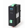
RS-485 Self-healing Ring Fiber Optic Converter
The Rs-485 Self-healing Ring Fiber Optic Transmission series products provide an optical self-healing ring network for RS-485/422 data interfaces over two multi mode or single mode optical fibers. The system offers maximum reliability as it can recover simultaneous faults or failures in two different locations and has contact closure outputs on each module to clearly indicate any fault location. The self-healing ring consists of two opposing data paths, ring A and ring B. Under normal operation only the primary path (ring A) is used for data transfer. If a fault is detected, the data is transferred to the secondary path (ring B) without interruption to the communications network.
The series is available in wall mount, DIN rail or 3U chassis card.
Product Features of the RS485 Self-healing Ring fiber optic converter
Supports RS422 and RS485
Multi mode and single mode solutions
Contact closure alarm outputs per station
Dual redundant power supply
DIN rail and 3U chassis card
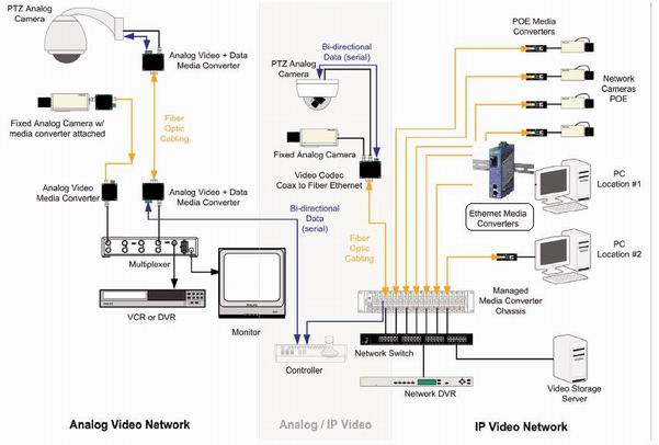
Typical System Configuration of the RS-485 Self-healing Ring Fiber Optic Converter:

Other Specifications:
| Data | |
| Data Formats | RS485 or RS422 |
| RS232 Data Rate | 115.2kbps |
| RS422 / 485 Data Rate | 512 kbps or 1Mkbps |
| Bit Error Rate | <1 x 10-12 |
| Connectors | |
| Data | Screw Block Terminal |
| Fiber | ST, SC or FC (ST fitted as standard) |
| Environmental | |
| Operating Temperat ure | - 3 0 C--- +70 C |
| Storage Temperature | - 40 C--- +85C |
| Operating Humidity | 0- 95% |
| MTBF | >100,000 Hours |
| Optical | |
| Fiber | Multi mode or single mode |
| Wavelength | MM: 850/1310nm, SM: 1310/1550nm |
| Number of fibers | 4 or 2 |
| POWER | |
| Power Input | AC 220V 110v or DC+110V +5V +12V +24V +48V Option |
| Mechanical | |
| Dimensions | DIN Rail 43*88.5*124.5mm(W*D*H) |
Ordering Information:
|
Model Number |
Description |
Fiber No. |
Fiber Mode |
Fiber Connector |
|
HFD-FO-485-R2M |
Self-healing Ring,Single Fiber(BI-DI), 2km |
2 |
Multi Mode |
ST/SC/FC |
|
HFD-FO-485-R4M |
Self-healing Ring,Dual Fiber, 2km |
4 |
Multi Mode |
ST/SC/FC |
|
HFD-FO-485-R2S |
Self-healing Ring,Single Fiber(BI-DI), 20km |
2 |
Single Mode |
ST/SC/FC |
|
HFD-FO-485-R4S |
Self-healing Ring,Dual Fiber, 20km |
4 |
Single Mode |
ST/SC/FC |
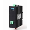
RS-485 Multi-drop BUS Fiber Optic Converter

HFD-FO-485 RS-485 Multi-Drop Bus Fiber Optic converter
The RS-485 Multi-Drop Bus Fiber Optic Converter products provide an optical bus network for RS-422 or RS-485 data interfaces over a pair of multimode or singlemode optical fibers. The Terminal module units operate as the end or terminal points and provide an electrical connection and a two fibre optical connection. The Repeater module units act as in-line repeater stations and provide a single electrical connection and two optical connections, one upstream and one downstream. This series is available in either wall mount, DIN rail or 3U chassis card configurations.
Product Features
Multi protocol data interface
Switchable termination and biasing
Multimode and singlemode
DIN and 3U chassis card
Dual redundant power supply
| Data | |
| Data Formats | RS232,RS422,RS485 |
| RS232 Data Rate | 115.2kbps |
| RS422 / 485 Data Rate | 512 kbps or 1Mkbps |
| Bit Error Rate | <1 x 10-12 |
| Connectors | |
| Data | Screw Block Terminal |
| Fiber | ST, SC or FC (ST fitted as standard) |
| Environmental | |
| Operating Temperat ure | - 3 0 C--- +70 C |
| Storage Temperature | - 40 C--- +85 C |
| Operating Humidity | 0- 95% |
| MTBF | >100,000 Hours |
| Optical | |
| Fiber | Multi mode or single mode |
| Wavelength | MM: 850/1310nm, SM: 1310/1550nm |
| Number of fibers | 4 or 2 |
| Power | |
| Power Input | AC 220V 110v or DC+110V +5V +12V +24V +48V Option |
| Mechanical | |
| Dimensions | DIN Rail 43*88.5*124.5mm(W*D*H) |
Ordering Information:
|
Model Number |
Description |
Fiber No. |
Fiber Mode |
Fiber Connector |
|
HFD-FO-485-M2M |
Multi Drop Bus Link,Dual Fiber(BI-DI), 2km |
2 |
Multi Mode |
ST/SC/FC |
|
HFD-FO-485-M4M |
Multi Drop Bus Link,4 Fiber, 2km |
4 |
Multi Mode |
ST/SC/FC |
|
HFD-FO-485-M2S |
Multi Drop Bus Link,Dual Fiber(BI-DI), 20km |
2 |
Single Mode |
ST/SC/FC |
|
HFD-FO-485-M4S |
Multi Drop Bus Link,4 Fiber, 20km |
4 |
Single Mode |
ST/SC/FC |
RS-485 Fiber Optic Converter(Point to Point)
HFD-FO-485 RS-485/422 Fiber Optic Converter
The HFD RS-485/422 Fiber Optic Converter data series uses the most advanced digital technologies to provide excellent repeatable performance for today's data systems. It supports transmission of one bi-directional data channel over one multimode or singlemode optical fiber. RS422 and RS485 (2 wire & 4 wire) standards are fully supported. The plug-and-play design ensures ease of installation with no electrical or optical adjustment needed. LED indicators are provided to show the operational status of the unit clearly.
The series is available in compact wall mount or 3U chassis card.
The RS-485/422 Series converter is equipped with a multiple interface circuit that can handle RS-485/422 serial interfaces and multi-mode or single- mode fiber. RS-485/422 converters are used to extend serial transmission distance up to 2 km (multi-mode fiber) or up to 20-100km (single- mode fiber)...Auto Baud Rate DetectionThe RS-485/422 Series incorporates a method for automatically detecting the serial signal baud rate by hardware. This is an extremely convenient feature for the user. Even if a device's baud rate is changed, the signal will still be transmitted through the RS-485/422to fiber converter without any problem.
Product Features of the RS485/422 to Fiber Converter:
Supports RS422 and RS485
Multimode and singlemode solutions
Switchable 120Ω Termination and biasing
LED indicators provide quick diagnosis of all important system parameters
Up to 14 units in a 3U chassis
Compact and 3U chassis card configuration, Dual power supplies
Technical Specs of the RS485/422 Fiber Optic Converter
| Data | |
| Data Formats | RS422,RS485 |
| RS232 Data Rate | 115.2kbps |
| RS422 / 485 Data Rate | 512 kbps or 1Mkbps |
| Bit Error Rate | <1 x 10-12 |
| Connectors | |
| Data | Screw Block Terminal |
| Fiber | ST, SC or FC (ST fitted as standard) |
| Environmental | |
| Operating Temperat ure | - 3 0 C--- +70 C |
| Storage Temperature | - 3 0 C--- +70 C |
| Operating Humidity | 0- 95% |
| MTBF | >100,000 Hours |
| Optical | |
| Fiber | Multi mode or Single mode |
| Wavelength | MM: 850/1310nm, SM: 1310/1550nm |
| Number of fibers | 2 or 1 |
| POWER | |
| Power Input | AC 220V 110v or DC+110V +5V +12V +24V +48V Option |
| Mechanical | |
| Dimensions | DIN Rail 43*88.5*124.5mm(W*D*H) |
Ordering Information:
|
Model Number |
Description |
Fiber No. |
Fiber Mode |
Fiber Connector |
|
HFD-FO-485-P1M |
Point to point Link,Single Fiber(BI-DI), 2km |
1 |
Multi Mode |
ST/SC/FC |
|
HFD-FO-485-P2M |
Point to point Link,Dual Fiber, 2km |
2 |
Multi Mode |
ST/SC/FC |
|
HFD-FO-485-P1S |
Point to point Link,Single Fiber(BI-DI), 20km |
1 |
Single Mode |
ST/SC/FC |
|
HFD-FO-485-P2S |
Point to point Link,Dual Fiber, 20km |
2 |
Single Mode |
ST/SC/FC |
10/100M Industrial Fiber Media Converter
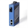
The HFD Series Industrial media converter is fully assembled using SMT components for stability and reliability.
|
ETHERNET |
|
|
Supporting standards |
IEEE802.3 10Base-T, 100Base-T |
|
Data Rate |
10/100Mbps auto-sensing, Full Duplex or Half Duplex |
|
Physical Interface |
RJ45, DCE interface |
|
OPTICAL |
|
|
Number of Fibers |
2 or 1 |
|
Wavelength |
SM:1310/1550nm, MM:850/1310nm |
|
Fiber Type |
9/125μ m(SM),62.5/125um(MM) |
|
Distance |
0 ~ 20km(SM), 0~2km(MM) |
|
Connector Type |
ST/FC/SC |
|
GENERAL |
|
|
Operating Temperature |
-40 ~ 70C / -40 ~ +158F |
|
Relative Humidity |
0 ~ 95% non-condensing |
|
Mean Time Between Failure (MTBF) |
> 600, 000hrs |
|
Power Supply Adaptors |
AC 220V 110v or DC+110V, +5V, +12V, +24V, +48V Option |
|
Enclosure Color |
Blue |
|
Dimensions ( H× W× D ) |
DIN Rail 120*30*88mm |
Case Topology
Odering Information:
|
Model Number |
Description |
Fiber No. |
Fiber Mode |
Fiber Connector |
|
HFD-FO-100M-P1M |
Point to point Link,Single Fiber(BI-DI), 2km |
1 |
Multi Mode |
ST/SC/FC |
|
HFD-FO-100M-P2M |
Point to point Link,Dual Fiber, 2km |
2 |
Multi Mode |
ST/SC/FC |
|
HFD-FO-100M-P1S |
Point to point Link,Single Fiber(BI-DI), 20km |
1 |
Single Mode |
ST/SC/FC |
|
HFD-FO-100M-P2S |
Point to point Link,Dual Fiber, 20km |
2 |
Single Mode |
ST/SC/FC |
GPS Time Server(Multi Time Codes Output)
GPS time server(GPS Single source/Irig-B/NTP/SNTP/DP9/RS485/Fiber Optic Outputs)
The Bueno SY series of GPS Standard Time Synchoronous Clock are specifically for power system, automatizatio system, communicate system and traffic system that need high-precise time requirer.Our system is based on GPS or Beidou, and the precision of time is 1µs. The facility is secondary developed with the GPS receiver that made by the special factory of United States. It can track 12 GPS satellites at the same time, and selects the best satellite automaticly for locating and timing. It outputs 1PPS, 1PPM, 1PPH time pulse and UTC time ,and the synchronous precision is 1µs, and it can measure the industrial frequency, and outputs date, time, cycle clock, cycle, clock difference, safe running days, and so on through RS232 serial with two formats. It is selected to used by automatization facilities that need standard time in electric power system.The facility adopted the technology of the united of software and hardware, and made good use of the potential of GPS receiver, so it has some characters such as high security, strong function, high precision, good proportion of capability and price, operate conveniently and so on,and it can afford to the requirement of time synchronous in electric power system,automatization system, communicate system and traffic system. With its extendly used, the development of some automatization technologies such as accident analysis, trouble range measurement and relay protection and so on will be promoted and improved greatly.
2 Technical parameter:
1. Receiving frequency:1575.42MHZ, it can track 8-12 GPS satellites at the same time.
2. Antenna radio sentivity:-166dbw, with 30 metres wire. If the wire is not long enough, customer can prolong it by himself by selection of coaxial-cable that attenuation of
1.56GHZ is not more than 0.7db per metre, the attenuation of prolonged cable is not more than 5db.
3. Capture time: from 20 seconds to 2 minutes (Annotate: the outputs of synchronous clock are all isolated by photoelectricity coupling and output 60ns)
4.1PPS output:
Timing varacity: 1µs Voltage: TTL voltage
Polarity: positive pulse Pulse width: about 100ms
Impedence: 50 Ώ Channel number: 1
Fore edge: <20ns
5.1PPM: output:
Timing varacity:: 1µs Voltage: TTL
Polarity: positive pulse Pulse width: about 100ms
Impedence: 50 Ώ Fore edge: <20ns
6.1PPH output:
Timing varacity:: 1µs Voltage: TTL
Polarity: positive pulse Pulse width: about 100ms
Impedence: 50 Ώ Fore edge: <20ns
7.Cycle precision: ±0.001
8.Industry frequency clock: the clock that is promoted by industry electricity is synchronous with standard clock when power is on.
9.Clock difference: that is standard clock minus industry frequency clock,synchronous time difference is zero,precision is 20 ms.
10.Longitude, latitude: where the electric power synchronous clock locates.
11.Display: 14 bits LCD display that includes cycle,date,time,longitude,latitude,industry frequency clock,clock difference (standard clock minus industry frequency clock).
12.RS232: output time code (year, month, day, hour, minute, second), industry frequency clock time(hour, minute, second), clock difference,cycle.
13.RS232: output “ST” format time code (selected by switching circuitry)
14.Power: AC110-220V or DC12-48V, 10%, 15W.
15.Size: standard industry 19 inch 2U box.1U and 3U can also be made.
16. We accept OEM orders for small quantity.
Ordering information:
|
Model |
Technical Parameters
|
Comment (Optional dual power) |
|
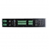
SY-GPS-2-G |
2 channel 1 PPS,2 channel 1 PPM , 1 channel 1 PPH (TTL/ active optical isolation and passive) 4 channel RS232, 2 channel RS485 (serial code) 2 "RS485 (IRIG-B (DC) difference), lose electric/out-of-step alarm to the 2 With expand output interface (can direct drive extension device)
|
Ac/dc power supply terminals wide input Optional NTP and optical output
|
|
SY-GPS-2-E16 |
2 channel 1 PPS,2 channel 1 PPM , 1 channel 1 PPH (TTL/ active optical isolation and passive) 4 channel RS232, 2 channel RS485 (serial code) 16channel"RS485 (IRIG-B (DC) difference), lose electric/out-of-step alarm to the 2 With expand output interface (can direct drive extension device)
|
Ac/dc power supply terminals wide input Optional NTP and optical output
|
|
SY-2U-TIME SY-2U-GPS-CPU X1 SY-2EX-IRIG-B(DC) X1 |
12 "RS485 (IRIG-B (DC) difference), lose electric/out-of-step alarm to the 2
|
2Uchassis Can be expanded plug-in |
|
SY-GPS-2-E32 |
2 channel 1 PPS,2 channel 1 PPM , 1 channel 1 PPH (TTL/ active optical isolation and passive) 4 channel RS232, 2 channel RS485 (serial code) 32 "RS485 (IRIG-B (DC) difference), lose electric/out-of-step alarm to the 2 With expand output interface (can direct drive extension device)
|
Ac/dc power supply terminals wide input Optional NTP and optical output
|
|
SY-2U-TIME SY-2U-GPS-CPU X1 SY-2EX-IRIG-B(DC) X3 |
32channel"RS485 (IRIG-B (DC) difference), lose electric/out-of-step alarm to the 2 |
2U chassis Can be expanded plug-in |
|
SY-GPS-2-FS16 (PPS OutPut) |
2 channel 1 PPS,2 channel 1 PPM , 1 channel 1 PPH (TTL/ active optical isolation and passive) 4 channel RS232, 2 channel RS485 (serial code) 2 "RS485 (IRIG-B (DC) difference), 16 channel 1 PPS / 1 PPM high-pressure high-speed photoelectric isolated active and passive output lose electric/out-of-step alarm to the 2 With expand output interface (can direct drive extension device) |
Ac/dc power supply terminals wide input Optional NTP and optical output
|
|
SY-GPS-2-FM16 (PPM ,Pulse Per Minute Output) |
|
|
|
SY-2U-TIME SY-2U-GPS-CPU X1 SY-2EX-1PPS/1PPM X1 |
12 "RS485 (IRIG-B (DC) difference), , lose electric/out-of-step alarm to the 2
|
2U chassis
|
|
SY-GPS-2-FS32(PPS Output) |
2 channel 1 PPS,2 channel 1 PPM , 1 channel 1 PPH (TTL/ active optical isolation and passive) 4 channel RS232, 2 channel RS485 (serial code) 2 "RS485 (IRIG-B (DC) difference), 32 channel 1 PPS / 1 PPM high-pressure high-speed photoelectric isolated active and passive output lose electric/out-of-step alarm to the 2 With expand output interface (can direct drive extension device) |
Ac/dc power supply terminals wide input Optional NTP and optical output
|
|
SY-GPS-2-FM32 (PPM ,Pulse Per Minute Output)) |
|
|
|
SY-2U-TIME SY-2U-GPS-CPU X1 SY-2EX-1PPS/1PPM X3 |
36 "RS485 (IRIG-B (DC) difference), , lose electric/out-of-step alarm to the 2
|
2U chassis |
|
SY-GPS-2-NET |
2 channel 1 PPS,2 channel 1 PPM , 1 channel 1 PPH (TTL/ active optical isolation and passive) 4 channel RS232, 2 channel RS485 (serial code) 2 "RS485 (IRIG-B (DC) difference), lose electric/out-of-step alarm to the 2 With expand output interface (can direct drive extension device) 2 "NTP/TCP network time output
|
Ac/dc power supply terminals wide input. Optional fiber optical output
|
GPS Antenna
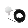
GPS antenne, High compact antenna, corrosion-proof PC (polycarbonate) resin, 100% waterproof, Low Noise Amplifier.The length can be from 30 meters to 500meters long.The Buenoptic GPS antenna can be use for GPS clocks,marine and other important areas.
PHYSICAL - GPS ANTENNA
|
Enclosure |
High compact, corrosion-proof PC (polycarbonate) resin |
|
Construction |
Hermetically sealed, fully waterproof |
|
Dimensions |
90mm(D) X 110mm(H) |
|
Weight |
65g (w/o cable & connector) |
|
Mounting |
Pole mount to 1-14 threaded pipe |
* The dimension and weight depend on the length of wire.
CABLE & CONNECTOR
|
RF cable |
10m RG-59 |
|
Connector |
BNC or TNC option |
ENVIRONMENTAL
|
Operating temperature |
-30 ~ +85 |
|
Storage temperature |
-40 ~ +90 |
|
Relative humidity |
95% non-condensing |
|
Waterproof |
100% waterproof |
ELECTRICAL
|
A. Antenna Element |
||
|
|
Center Frequency |
1575.42 MHz ± 1.023 MHz |
|
|
Absolute gain zenith |
+5 dB typical |
|
|
Absolute gain 10° |
-1 dB typical |
|
|
Axial ratio |
3 dB max |
|
|
Output VSWR |
1.5 max |
|
|
Output impedance |
50 ohm |
|
B. Low Noise Amplifier |
||
|
|
Center Frequency |
1575.42 MHz |
|
|
Power gain |
27 dB typical |
|
|
Band width |
2 MHz min. |
|
|
Noise figure |
1.5 max |
|
|
Out band attenuation |
20 dB min @Fo ±50MHz |
|
|
Supply voltage |
3.3 ~ 5.0 VDC |
|
|
Current consumption |
Maximum 12mA |
|
|
VSWR |
2.0 max |
|
|
Output impedance |
50 ohm |
|
C. Overall Performance (Antenna Element, LNA and Cable) |
||
|
|
Center frequency |
1575.42 MHz |
|
|
Gain |
26 dB min |
|
|
Noise figure |
2.0 max |
|
|
Band width |
2 MHz min |
|
|
Axial ratio3 dB max |
3 dB max |
|
|
VSWR |
2.0 max |
|
|
Output impedance |
50 ohm |