Sidebar
News Press

Administrator
Our CAN Bus Fiber Optic Converter with Multi-drop Bus applied in Swedish Project
BE's CAN Bus multi-drop bus fiber optic converters are recently adopted by Swedish project recommended by ABB in Sweden. The project used some Multi-drop bus CAN BUS fiber optic converters to connect to the PLCs, the multi-drop bus fiber solution helped the customer save cost and simplified the wiring of the network. This is our another success in Sweden.Please download the attached file for reference or case study.
Nanjing Became the largest power automation industrial base in China
Recently, China State Grid Nanjing Automation Co., LTD. (hereinafter referred to as "guodian south") investment 1. The first phase of Jiangning science and technology park, which has been constructed by 400 million yuan, has been put into operation, and the characteristic industry of Nanjing electric power automation has been pushed to the front desk again. It is reported, as since the ranks, south red coverage and rapid growth of the power backbone enterprises, following a highly competitive advantage of industry cluster has been formed in Nanjing, Nanjing is becoming the nation's largest electric power automation industry base.
The domestic market share is more than 80%
In the field of electric power automation, Nanjing has obvious competitive advantage, especially in relay protection, substation automation, power system, MIS and other project is a national leader, domestic market share of 80% or more. In foreign markets, Nanjing electric power automation industry also occupies a place, successively awarded Pakistan nuclear power project, Nepal capital city power grid project, Malaysia thermal power project, etc.
Based on the market position, the state ministry of science and technology more than half a month ago officially awarded title of "national electric power industry base" jiangning area, nanjing, at the same time, the south, the bartender, guodian south from mainland, neusoft Jin Zhi, CLP, dongda electric companies have been approved for the base of the first batch of backbone enterprises.
To generate an industrial chain with annual output of ten billion yuan
Guodian, head of the south since the nanjing daily reporter interview, the nanjing electric power automation in addition to several leading enterprises, there are 30 or so small and medium-sized enterprises engaged in the industry, formed the obvious market division of labor. In relay protection, for example, since the ranks, south red after confirmed big companies such as the main production of more than 220 kv, 35 kv and below is basically some small and medium-sized enterprises in the production, add up the annual sales revenue of large and small enterprises, more than 50 one hundred million yuan, of which light since the ranks, south the bartender was contributed more than 90%.
More significantly, the cluster of these enterprises has also led to the development of its upstream and downstream industries. For example, the phoenix company in jiangning produces a pair of terminals for the power automation products. According to the incomplete statistics of relevant departments, if the output value of this piece is added, the output value of the entire industrial chain of nanjing electric power automation will reach ten billion yuan.
Core technology achievement "hegemonic" position
Nanjing is not but the automation industry production base, are also important research and development base, holds the industry development at the core of cutting-edge technology, thus achievement of nanjing "overlord" position in the field.
It is understood that these are quite a number of core technologies to fill the domestic blank, such as the first set of transistor circuit relay protection, the first set of digital integrated movement device, the first complete with 500 kv substation, transformer, bus and reactor static protection device, such as the first set of digital line protection device, the first set of microcomputer protection device for 600000 mw and below unit, the first set of distribution of distributed integrated substation automation system, the first set of USES the 32-bit computer digital line protection device, etc., are all "made in Nanjing".
CAN Bus to Fiber Optic Converter Application in Film Motion Control System
BE's CAN Bus to fiber optic converter successfully installed in DARBY FILM's Motion Control Systems.
Darby Film is based out of the Toronto area but Darby has worked throughout Canada, South America and much of Europe. Darby’s equipment knowledge and dedication to making your job a success shows in his long list of repeat clientèle.With the help of CAN Bus fiber optic converter, the motion film system controlled by PLC which is based on CAN protocol can strengthen the filming distances to 2km.
What is CAN I Bus and EtherCat?
Can-I-Bus is the debut album by rapper Canibus, released on September 8, 1998 through Universal Records. The album was released after the rapper's success with his LL Cool J diss track, "Second Round K.O.", which was included on Can-I-Bus, with additional support from heavyweight boxer Mike Tyson.
However, the album received mixed reviews. The beats, created mostly by Wyclef Jean, were criticized for their blandness and unoriginality (with a fair amount of the criticism coming from Canibus), but lyrically, the album was praised. Tower Records referred to Canibus as "one of the most innovative new MCs in hip-hop. With Can-I-Bus, the debut album, Canibus delivers more of the battle-rhyme lyrics that are his stock in trade. Still, he manages to cover new ground with conceptually strong cuts like 'I Honor U,' which is dedicated to his mother. With his lyrical skills, Canibus represents the elements that helped build rap music." The album was certified gold by the RIAA. The song "How We Roll" also appeared on the bonus 3rd disc of Eightball's album Lost.
EtherCat
EtherCAT - Ethernet for Control Automation Technology - is an Ethernet-based fieldbus system, invented by Beckhoff Automation. The protocol is standardized in IEC 61158 and is suitable for both hard and soft real-time requirements in automation technology.
The goal during development of EtherCAT was to apply Ethernet for automation applications requiring short data update times (also called cycle times; ≤ 100 µs) with low communication jitter (for precise synchronization purposes; ≤ 1 µs) and reduced hardware costs.
EtherCAT Features
Functional Principle
File:EthercatOperatingPrinciple.webm
Frame processing
With EtherCAT, the standard Ethernet packet or frame (according to IEEE 802.3) is no longer received, interpreted, and copied as process data at every node. The EtherCAT slave devices read the data addressed to them while the telegram passes through the device, processing data "on the fly". Similarly, input data are inserted while the telegram passes through. A frame is not completely received before being processed; instead processing starts as soon as possible. Sending is also conducted with a minimum delay of small bit times. Typically the entire network can be addressed with just one frame.
ISO/OSI Reference Model
This graphics shows the ISO OSI Model related to EtherCAT
Figure Caption:
The TCP/IP Stack shown is not needed for typical fieldbus devices.
EtherCAT master can access all data including name and data types of an EtherCAT slave without complex tools.
EtherCAT uses Standard Ethernet (IEEE 802.3 - Ethernet MAC and PHY) without modifications.
Protocol
The EtherCAT protocol is optimized for process data and is transported directly within the standard IEEE 802.3 Ethernet frame using Ethertype 0x88a4. It may consist of several sub-telegrams, each serving a particular memory area of the logical process images that can be up to 4 gigabytes in size. The data sequence is independent of the physical order of the nodes in the network; addressing can be in any order. Broadcast, multicast and communication between slaves is possible, but must be initiated by the master device. If IP routing is required, the EtherCAT protocol can be inserted into UDP/IP datagrams. This also enables any control with Ethernet protocol stack to address EtherCAT systems.
Performance
Short cycle times can be achieved since the host microprocessors in the slave devices are not involved in the processing of the Ethernet packets to transfer the process images. All process data communication is handled in the slave controller hardware. Combined with the functional principle this makes EtherCAT a high performance distributed I/O system: Process data exchange with 1000 distributed digital I/O takes about 30 µs, which is typical for a transfer of 125 byte over 100Mbit/s Ethernet. Data for and from 100 servo axis can be updated with up to 10 kHz. Typical network update rates are 1–30 kHz, but EtherCAT can be used with slower cycle times, too, if the DMA load is too high on your PC.
The bandwidth utilization is maximized, as each node and each date do not require a separate frame. Thus, extremely short cycle times of ≤ 100 µs are achievable. By using the full-duplex features of 100BASE-TX, effective data rates of more than 100 Mbit/s (> 90% user data rate of 2x100 Mbit/s) can be achieved.
The EtherCAT technology principle is scalable and not bound to 100 Mbit/s. A future extension to Gigabit Ethernet is possible, but is not in preparation at the moment since the EtherCAT performance is sufficient at 100 Mbit/s.
Topology
Using full-duplex Ethernet physical layers, the EtherCAT slave controllers close an open port automatically and return the Ethernet frame if no downstream device is detected. Slave devices may have one, two, or more ports. Due to these features EtherCAT enables a multitude of network topologies, including line, tree, ring, star, or any combination thereof. The protocol also enables a multitude of communication features such as cable redundancy, Hot Connect of segments, change of devices during operation, or even master redundancy with Hot Standby.
Thus the combination of the topology variations and different network architectures, e.g. sub-ordinated or neighboring control systems with consistent synchronization, enables numerous possibilities. Additional switches are not required. The physics of Ethernet allow a cable length of up to 100 m (300 ft) between two nodes, so the E-bus (LVDS) is only intended for use as the physical layer for modular devices. For each cable path, the signal variant can be chosen individually. For higher distances, or the complete galvanic isolation between two slaves, fiber optic cables are used. With single-mode fiber, distances up to 20 km between two nodes can be bridged. Since a total of 65,535 nodes per network segment can be connected, the network extension is nearly unlimited.
Synchronization
For synchronization a distributed clock mechanism is applied, which leads to very low jitter, significantly less than 1 µs, even if the communication cycle jitters, which is equivalent to the IEEE 1588 Precision Time Protocol standard (PTP). Therefore, EtherCAT does not require special hardware in the master device and can be implemented in software on any standard Ethernet MAC, even without dedicated communication coprocessor.
The typical process of establishing a distributed clock is initiated by the master by sending a broadcast to all slaves to a certain address. Upon reception of this message, all slaves will latch the value of their internal clock twice, once when the message is received and once when it returns (remember EtherCAT has a ring topology). The master can then read all latched values and calculate the delay for each slave. This process can be repeated as many times as required to reduce jitter and average out values. Total delays are calculated for each slave depending on their position in the slave-ring and will be uploaded to an offset register. Finally the master issues a broadcast readwrite on the system clock, which will make the first slave the reference clock and forcing all other slaves to set their internal clock appropriately with the now known offset.
To keep the clocks synchronised after initialization, the master or slave must regularly send out the broadcast again to counter any effects of speed difference between the internal clocks of each slave. Each slave should adjust the speed of their internal clock or implement an internal correction mechanism whenever they have to adjust.
The system clock is specified as a 64 bit counter with a base unit of 1ns starting at January 1, 2000, 0:00.
Diagnosis
The fast, precise detection of disturbances is one of many diagnostic features of EtherCAT.
Bit errors during transmission are detected reliably by the analysis of the CRC check sum: the 32 bit CRC polynomial has a minimum Hamming distance of 4. Besides the error detection and localization protocol, the transmission physics and topology of the EtherCAT system allow individual quality monitoring of every single transmission path. The automated analysis of the according error counters enables the exact localization of critical network segments.
More info to follow in the chapter titled "Monitoring".
Device Profiles
The device profiles describe the application parameters and functional behavior of the devices, including device-specific state machines. The following software interfaces are provided for existing device profiles. Thus the migration to EtherCAT by adjusting the firmware and the hardware is simplified significantly.
CAN application protocol over EtherCAT (CoE)
CANopen™ devices and application profiles are available for an extensive selection of device categories and applications: I/O modules, drives (e.g., drive profile CiA 402 standardized as IEC 61800-7-201/301), encoders (CiA 406), proportional valves, hydraulic controllers (CiA 408), or application profiles. In this case, EtherCAT replaces CAN.
Servodrive-Profile over EtherCAT (SoE)
SERCOS interface™ is a powerful real-time communication interface, ideal for demanding motion control applications. The SERCOS profile for servo drives and communication technology are standardized in IEC 61800-7. This standard also contains the mapping of the SERCOS servo drive profile to EtherCAT (IEC 61800-7-304).
Other Protocols
Ethernet over EtherCAT (EoE)
Any Ethernet device can be connected within the EtherCAT segment via switch ports. The Ethernet frames are tunneled via the EtherCAT protocol, as is normal for internet protocols (e.g., TCP/IP, VPN, PPPoE (DSL), etc.). The EtherCAT network is fully transparent for the Ethernet devices, and the real-time features of EtherCAT are not disturbed.
Functional Safety: Safety over EtherCAT (FSoE)
In parallel to the development of EtherCAT, a fieldbus-independent safety protocol has been developed. For EtherCAT, it is available as "Safety over EtherCAT" (FSoE = Fail Safe over EtherCAT). With FSoE, functional safety with EtherCAT can be realized. The protocol as well as the implementation are certified by TÜV and meet the requirements of the Safety Integrity Level 3 according to IEC 61508. Since 2010, Safety over EtherCAT is internationally standardized to IEC 61784-3-12. EtherCAT provides a single-channel communication system for transferring safe and non-safe information. The transport medium is regarded as a black channel,[1] and thus is not included in safety considerations.
Monitoring
Since EtherCAT uses standard Ethernet frames according to IEEE 802.3, any standard Ethernet tool can be used to monitor the EtherCAT communication. Additionally, there is free-of-charge parser software for Wireshark (formerly Ethereal, an open source monitoring tool) and the Microsoft network monitor, with which recorded EtherCAT data traffic can be comfortably prepared and displayed.
Gateways
By using gateways, existing networks such as CANopen, DeviceNet, or Profibus, can be integrated into the EtherCAT environment seamlessly. Furthermore, gateways provide a trip-free migration path from a traditional fieldbus to EtherCAT, reducing further investment costs.
Thanks to the performance of EtherCAT, communication with external fieldbus masters is as fast as with traditional cards connected via PCI or other backbone buses. Since decentralized fieldbus interfaces lead to shorter extensions, they can be operated with even higher baud rates than would have been possible with the traditional architecture.
Implementation
General
EtherCAT Technology Group (ETG) encourages and expects companies that develop EtherCAT products to join ETG, so that they can get an EtherCAT Vendor-ID, get access to the full documentation, to the developers forum and to the slave stack code, that Beckhoff provides free of charge to ETG members.
Master
Masters can be implemented as a software solution on any Ethernet MAC. Different manufacturers provide code for different operating systems, including several open-source projects.
Due to the relocated mapping on the slave hardware, demands are reduced for CPU performance of the master. The master already contains the data as a readily sorted process image.
Slave
Contrary to the operation of standard Ethernet, the slaves process the EtherCAT frames on the fly. This requires the use of hardware-integrated EtherCAT Slave Controllers (ESC) in the slaves. ESCs are also available as ASICs or based on FPGAs. Since the beginning of 2012, standard microprocessors with EtherCAT slave interfaces are also available.
For simple devices, no additional microcontroller is required. In more complex devices, however, the communication performance of EtherCAT is nearly independent of the performance of the used controller. Thus the requirements for the microcontroller are determined by the local application, e.g. the drive control.
There is a choice of development boards, both from the EtherCAT Slave Controller suppliers and from third party vendors. There are also open-source projects for EtherCAT slave device development boards, such as SOES and ArduCAT.
Application Examples
Typical application fields for EtherCAT are machine controls (e.g. semiconductor tools, metal forming, packaging, injection molding, assembly systems, printing machines, robotics). Remote controlled hump yard facilities used in the railroad industry.
Control and regulation
For the control and regulation of physical processes, high data integrity, data security, and synchronicity is required. EtherCAT has been designed especially for these kinds of applications and meets all demands for fast controls.
Measurement systems
Modern measurement systems are characterized by multi-channeling, synchronicity, and accuracy. Due to the advanced protocol features of EtherCAT, efficient synchronous data throughput is assured. The network features based on Ethernet enable a measurement network with distributed measurement modules.
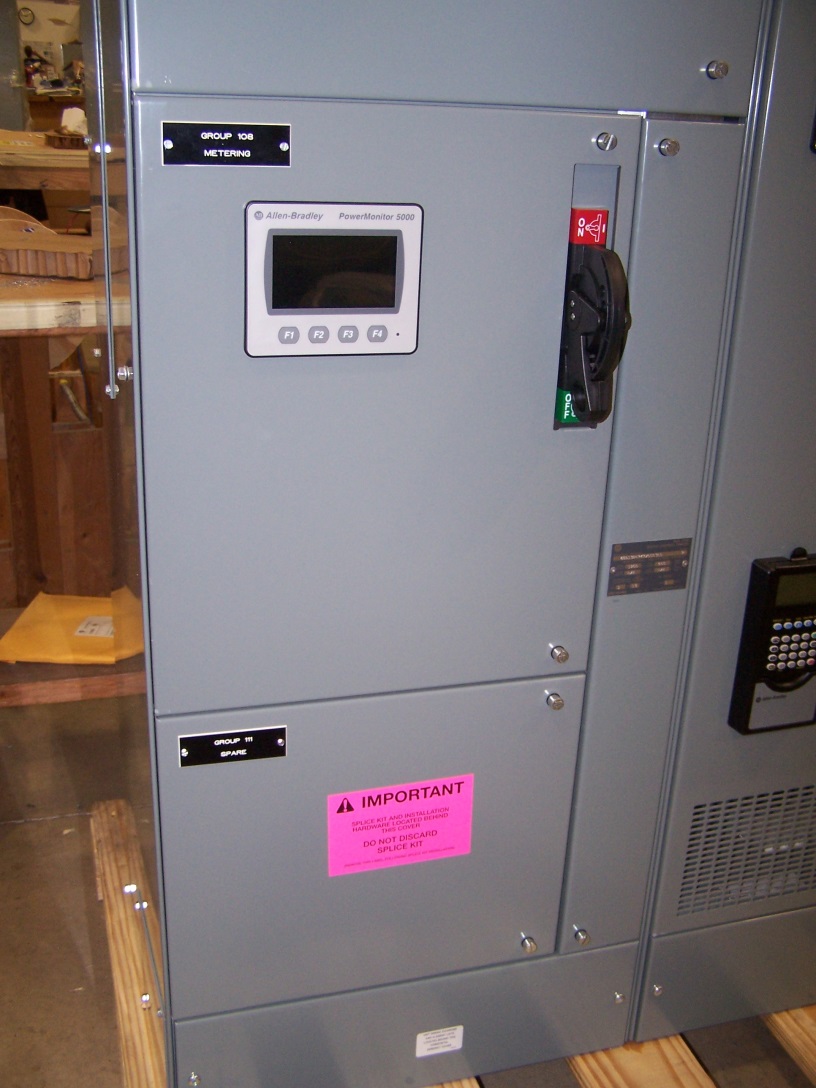
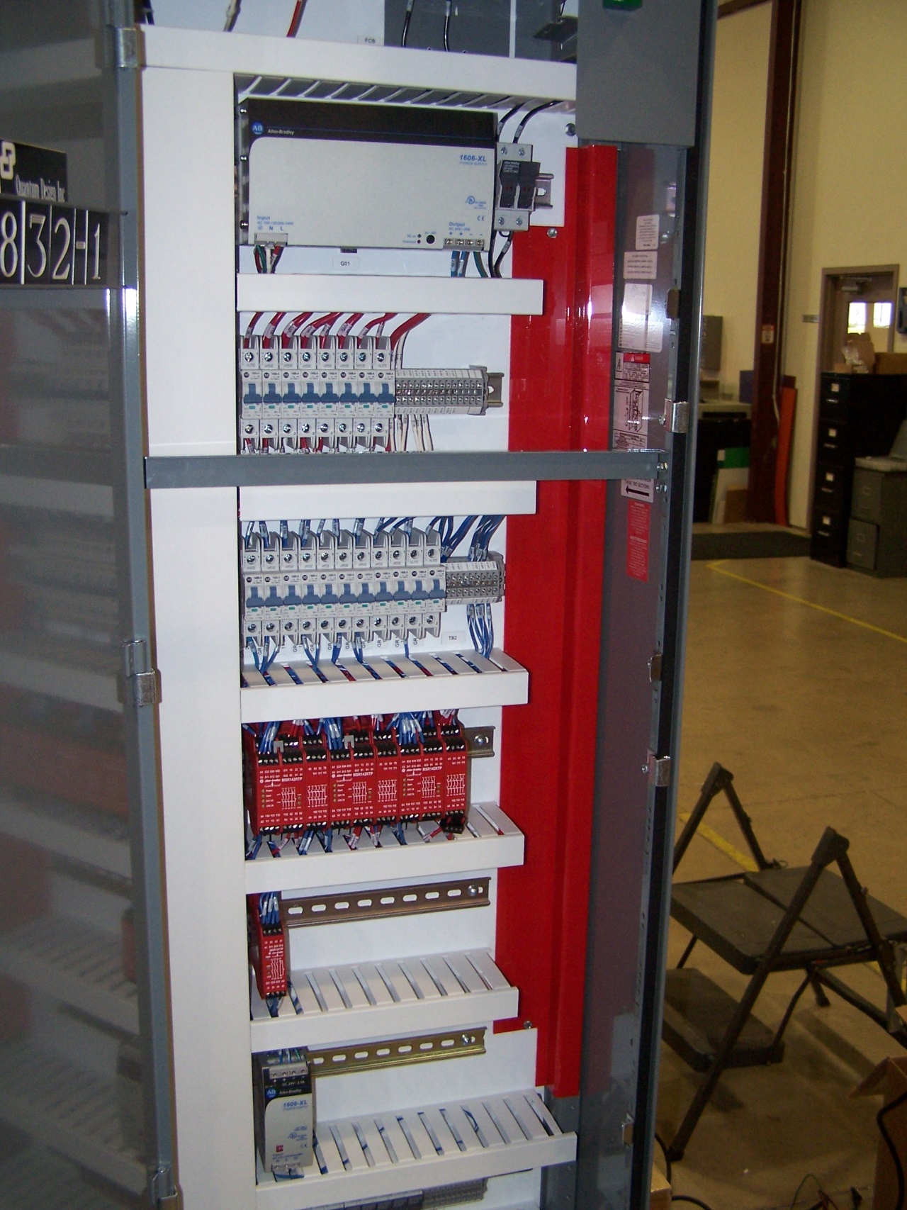
Motor Control uses Ethernet remotely with significantly less wiring
B E Design designs Motor Control Center using Ethernet increasing safety and allowing factory personnel access to important information remotely.
What industries would find this most relevant?
Engineering or system integration services
Food, beverage, or tobacco
Industrial machinery
Which of your engineering specialties does this project best illustrate?
Automation and control engineering (including designs and implementation)
Control panels (including fabrication, installation, and UL listing)
Networking and communications (including fieldbus, Ethernet, and telemetry)
Describe the nature and scope of the project in greater detail
In the 1950s, Motor Control Centers were originally introduced and used by the automobile manufacturing industry which uses large numbers of electric motors. Today, they are used within many different industries for a variety of applications in industrial and commercial settings. With the advances in technology, a Motor Control Center no longer just turns a motor on and off. The newest generation of MCCs offer several options for communication, power monitoring/management and safety design;
Difference of Industrial Ethernet and Commercial Grade
What is an industrial Ethernet switch:
In terms of performance, there is no difference between an industrial Ethernet switch and an ordinary switch. From the network level, there are two layer switches, and of course three layers of switches. Industrial Ethernet switches in the product design and components selection is to have cultured, it is an industrial field use demand, the machinery, such as climate, electromagnetic environment is relatively poor, still be able to work properly, so, often can be widely used in the condition is relatively harsh industrial production scene.
Exchange industrial grade and commercial grade two
Industrial Ethernet switches are different from regular switches
1 Components
Industrial Ethernet switch components are more demanding, and better suited to the requirements of industrial production sites.
2 Mechanical environment
Industrial Ethernet switches can better adapt to the harsh mechanical environment, including shock resistance, impact resistance, corrosion resistance, dust proof, water proof, etc.
3 Climate environment
Industrial Ethernet switches can better adapt to poor weather conditions, including temperature and humidity.
4 Electromagnetic environment
The industrial Ethernet switch has strong resistance to electromagnetic interference.
5 Working voltage
The industrial Ethernet switch has a wide range of working voltages, while ordinary switches have higher voltage requirements.
6 Power supply design
General switches are basically single-power supply, whereas industrial switch power supply is generally double power backup.
7 Installation mode
Industrial Ethernet switches can be installed with DIN guide, rack and other installation. General switches are usually rack and desktop.
8 Heat dissipation mode
Industrial Ethernet switches generally use a fanless heat, whereas the general switch is fan cooling
Datasheet CAN to Multi Mode Fiber Optic Converter
Datasheet CAN to Single Mode Fiber Optic Converter
CAN Data frames's Structure and Format
Data Data frame structure

The data frames in Classical CAN and CAN FD comprises the same fields. The remote frame, only available in Classical CAN, has the same field structure as the data frame, but without a data field.
The SOF (start-of-frame) field is a fixed 1-bit field with a dominant bit level. It is followed by the arbitration field, which contains mainly the identifier bits and some protocol bits indicating the length of the CAN-ID and reserved bits. The next field is the control field with the information on the length of the data field (four data length code bits). Additionally, it provides some control bits, e.g. the FDF (FD format) bit distinguishing the two data link layer protocols, Classical CAN and CAN FD. The payload is in the data field. In Classical CAN, it features up to 8 byte and in CAN FD it can be up to 64 byte long. The following CRC field comprises a cyclic redundancy checksum (CRC) and in CAN FD an additional stuff-bit counter. The ACK (acknowledge) field is made of two bits. It is used to indicate a correct reception of the message. The last fields are the 7-bit EOF (end-of-fame) with fixed format (recessive bit-level) and the 3-bit IMF (intermission field) separating the frame from the next one.
Data data frame formats
The CAN data link layers distinguish between base frames (11-bit CAN-ID) and extended frames (29-bit CAN-ID). Base frames have a dominant IDE (ID extension) bit. This is why they win bus-arbitration against extended frames with the very same first bit-pattern. In order to distinguish between Classical CAN and CAN FD frames, the r1 reserved bit is transmitted recessively in CAN FD frames. Of course, this violates the Classical CAN specification. This means that legacy CAN controller chips destroy CAN FD communication. However, there are some migration paths that let you use legacy CAN implementations in CAN FD networks.

In the shown Classical CAN arbitration field examples, “0” represents a dominant and “1” a recessive bus-level (ID = identifier, SOF = start-of-frame, RTR= remote transmission request, SRR = substitute remote request, IDE = identifier extension)
The ISO 11898-1 standard introduces four different formats:
CBFF: Classical base frame format with 11-bit IDs
CEFF: Classical extended frame format with 29-bit IDs
FBFF: FD base frame format with 11-bit IDs
FEFF: FD extended frame format with 29-bit IDs
The formats differ in the control field (additional bits in FD frames), the data field length (Classical data frames are limited to a maximum of 8 byte, while FD data frames allow up to 64 byte), and the CRC field (different polynomials and additional safeguards for FD frames). Remote frames are not supported by the CAN FD protocol. CiA doesn’t recommend using remote frames. Remote frames request a data frame with the very same CAN-ID.
The Connection Ways of Fiber Media Converter
Fiber Optic Media Converter is a short twisted-pair electric signals and optical signals over long distances to swap the Ethernet transmission media conversion unit, also known as the photoelectric converter at many places. Products commonly used in Ethernet cable can't cover, optical fiber must be used to extend the transmission distance of actual network environment, and usually located in broadband metropolitan area network access layer of the application.
In traditional Ethernet, the medium of connection is the double stranded wire. The limits of twisted-pair transmission distance is about 200 meters, so short transmission distance of restricting the development of network, twisted pair is strongly influenced by electromagnetic interference at the same time, it also makes data communication quality is affected by the larger. The use of fiber optic media converter is used to change the connection medium in Ethernet to optical fiber. Optical fiber has low loss and high electromagnetic interference, in the network transmission distance from 200 m to 2 kilometers or even dozens of kilometers, even in the hundreds of kilometers, at the same time, also make the quality of data communication has greatly improved. He makes the connection between servers, relays, hubs, terminals and terminals more simple.
In practical applications, the fiber optic media converter basically has the following three basic connection mode: a circular, circular backbone of backbone network is to use the SPANNING TREE characteristics to build the backbone of the metropolitan area within the scope, this structure can be transformed into the reticular structure, suitable for high density on metropolitan area network at the center of the village, form the core backbone network fault tolerance. The loop backbone network supports IEEE 1Q and ISL network features to ensure that most mainstream backbone networks, such as vlans, TRUNK, etc., are compatible. The circular backbone network can form broadband virtual private networks in finance, government, education and other industries.
2, chain backbone chain backbone network using chain form the backbone of the connection can save a lot of light, suitable for the edge of the city and suburban county district construction of high bandwidth and low price of backbone network, the model can be used in the highway at the same time, such as oil, transmission line environment. Chain-shaped backbone support for ieee802.1q and ISL network characteristics, to ensure compatibility with most of the backbone network, can provide financial, government, education and other industries to form a broadband virtual private network. The chain backbone is a multimedia network that can provide images, voice, data, and real-time monitoring.
Three, user access system users access the system using 10 MBPS / 100 MBPS adaptive and 10 MBPS / 100 MBPS automatic conversion function, can join any client devices, don't need to prepare a variety of fiber optic transceivers, can provide a smooth upgrade scheme for network. At the same time using half duplex/full duplex adaptive and half duplex/full duplex automatic conversion function, can be in the client configuration of cheap half duplex HUB, several dozen times the client of the network to reduce costs, improve the competitiveness of the network operators. At the same time, the device's built-in exchange core increases the transmission efficiency of the connected device, reducing network broadcast, controlling the flow, detecting transmission failure.