Sidebar
News Press

Administrator
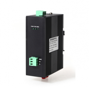
CAN Bus Optical Converter (Advanced New Version)
CAN Bus Optical Converter(Newly Released)
Product Description:
The BE-CAN-FO CAN to single mode and CAN to multi mode optical Converter support all the transmission speeds (transmission rates):0-1Mbps. The BE-CAN-FO-P2S & BE-CAN-FO-P2M is a repeater used to establish a connection between two CAN bus systems via single mode or multi mode fiber optic transmission medium. The BE-CAN-FO series is specially designed for converting the electrical CAN bus signal to fiber optic communication for transmission over single mode fiber optic cables.The setting or adjustment is dependent on the transmission rate. The BE-CAN-FO optical converter is developed out based on the growing market demand for CAN Bus long distance transmission without any cascading(attenuation).The transmission distance limitation of the CAN bus system will NOT be affected by different CAN baud rates. The total CAN bus communication distance can be extended over fiber optic cables. Bus errors on one CAN network will not affect the operation of another CAN network. The BE-CAN-FO-P2S & BE-CAN-FO-P2M is applied with the most advanced technology and CPU in the world,which is the foundation of the high rate transmission(1MB) over more than 20km without any cascading or delay.Thanks to the advanced technology and high performance,the BE-CAN-FO to Fiber Converters have been used in very important projects in the world.
Product Feature & Benefits:
- Buffering function:The BE-CAN-FO CAN Bus Fiber Optic Converter can protect the data from being lost.The isolation inside the optical converter can ensure the converters work normally under harsh environments.Anti-stream function,Buffering: 1000 frames.
- No cascading: The BE-CAN-FO has no cascading,no frame loss when data is at high rate or long distance transmission, the distance is NOT limited by the increased baud rate.
- Reliability: Compared with other brands,the BE-CAN-FO can help build up more stable and secure networks,it can maximumly reach 6500 frames/S.
- Buffer clearance: Clear the buffer in nominated time(For Option)
- High rate: Up to 1Mbps(SM;20km, MM:2km)
Applications:
- Control Systems
- Building Automation
- Factory Automation
- Distributed Data Acquisition
- Fire Panels
- Power Automation
- Military
- Industrial Automation
- Battery Control
- Filming industry
Other Specs:
|
Technical Data |
|
|
Voltage/power supply |
9 to 30V DC |
|
Operating voltage |
9 V to 30 V DC, typ. 24 V, |
|
Current consumption |
typ. 80 mA@24V |
|
Output voltage/current (Pin 6 Sub-D socket) |
5 V +5%,–10%/ 90 mA |
|
Signaling contact Signal transmission |
Max .switch DC24V@2A or This email address is being protected from spambots. You need JavaScript enabled to view it. |
|
Transmission rate |
0-1Mbps |
|
Setting transmission rate |
Rotary button or software |
|
Bit error rate |
< 10-9 |
|
Electrical port |
Terminal or DB9 |
|
Standard |
ISO-11898, CAN1.0 ,CAN2.0 , Device Net |
|
Optical ports |
1 or 2 (2 as standard) |
|
Wavelength |
MM:850/1310nm, SM:1310/1550nm |
|
optical power:– in glass fiber 9/125um – in glass fiber G 62.5/125 |
-9dBm – -18 dBm -13 dBm – -20 dBm |
|
Receiver sensitivity |
-34dBm |
|
Transmission distance:with glass fiber 9/125um with glass fiber G 62,5/125 |
0 – 20,000 m (0.3 dB/km) 0 – 3,000 m (2.0 dB/km) |
|
Connector |
ST/FC/SC |
|
Others |
|
|
Ambient temperature |
-30 °C to +70 °C |
|
Storage temperature |
–40 °C to +85 °C |
|
Relative humidity |
<95 %, non-condensing |
|
Protection class |
IP 30 |
|
Dimensions (W x H x D) |
86 x 29 x 155mm(W*D*H) |
|
Housing material/Color |
Die-cast zinc/Black |
|
Weight |
approx. 600 g |
Electromagnetic compatibility (EMC)
Limit class B (EN 55022)
EN 61000-4-2
EN 61000-4-3)
Burst: On power supply lines and shielded RS 485 bus lines: ±2 kV (EN 61000-4-4)
Surge: Power lines: ±1 kV symmetrical,Shielded RS 485 lines: ±2 kV asymmetrical (EN 61000-4-5)
Ordering Information:
|
Model Number |
Description |
Fiber No. |
Fiber Mode |
Fiber Connector |
|
BE-CAN-FO-P1M |
Point to point Link,Single Fiber(BI-DI), 2km |
1 |
Multi Mode |
ST/SC/FC |
|
BE-CAN-FO-P2M |
Point to point Link,Dual Fiber, 2km |
2 |
Multi Mode |
ST/SC/FC |
|
BE-CAN-FO-P1S |
Point to point Link,Single Fiber(BI-DI), 20km |
1 |
Single Mode |
ST/SC/FC |
|
BE-CAN-FO-P2S |
Point to point Link,Dual Fiber, 20km |
2 |
Single Mode |
ST/SC/FC |
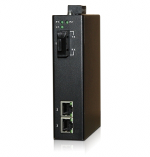
Gigabit(10/100/1000M) Industrial Media Converter New!
|
ETHERNET |
|
|
Supporting standards |
IEEE802.3 10Base-T, 100Base-T, 1000Base-T |
|
Data Rate |
10/100/1000Mbps auto-sensing, Full Duplex or Half Duplex |
|
Physical Interface |
RJ45, DCE interface, 2 ports |
|
OPTICAL |
|
|
Number of Fibers |
2 or 1 |
|
Wavelength |
SM:1310/1550nm MM: 850/1310nm |
|
Fiber Type |
9/125μm(SM) ,62.5/125μm(MM) |
|
Distance |
0 ~ 20km(SM),0~2km(MM) Option: 40/60/80/120km |
|
Connector Type |
ST/FC/SC |
|
GENERAL |
|
|
Operating Temperature |
-40 ~ 70˚C / -40 ~ +158ºF |
|
Relative Humidity |
0 ~ 95% non-condensing |
|
Mean Time Between Failure (MTBF) |
> 600,000hrs |
|
Power Supply Adaptors |
12~36V DC(Dual redundant power supplies) or 85~264VAC/77~300VDC(Single power supply) |
|
Enclosure Color |
Black |
|
Dimensions ( W x H x D) mm |
30x 125 x 88mm |
|
IP Grade |
IP40 |
|
Power Consumption |
≤ 3W |
|
Power Supply Protection |
Reverse connection, Overload |
|
Mount Way |
DIN Rail |
|
Warranty |
2 to 5 Years |
|
IEEE STANDARD |
|
|
IEEE 802.3 |
10BaseT Ethernet |
|
IEEE 802.3u |
100BaseT(X) and 100BaseFX Fast Ethernet |
|
IEEE 802.3ab |
1000BaseT(X) Ethernet |
|
IEEE 802.3z |
1000BaseX Ethernet |
|
IEEE 802.3x |
Flow Control |
|
CERTIFICATE |
|
|
EMC |
CE, FCC |
|
EMI |
FCC Part 15. CISPR(EN55022) class A |
|
EMS |
EN61000-4-2(ESD)Level 3, |
|
|
EN61000-4-3(RS)Level 3, |
|
|
EN61000-4-4(EFT)Level 3, |
|
|
EN61000-4-5(Surge)Level 3, |
|
|
EN61000-4-6(CS)Level 3, |
|
|
EN61000-4-8 |
|
Shock |
IEC60068-2-27 |
|
Freefall |
IEC60068-2-32 |
|
Vibration |
IEC60068-2-6 |
|
Green Product |
RoHS, WEEE |

|
Model Number |
Description |
Fiber No. |
Fiber Mode |
Fiber Connector |
|
HFD-FO-1000M2-P1M |
Point to point Link,Single Fiber(BI-DI), 2km |
1 |
Multi Mode |
ST/SC/FC |
|
HFD-FO-1000M2-P2M |
Point to point Link,Dual Fiber, 2km |
2 |
Multi Mode |
ST/SC/FC |
|
HFD-FO-1000M2-P1S |
Point to point Link,Single Fiber(BI-DI), 20km |
1 |
Single Mode |
ST/SC/FC |
|
HFD-FO-1000M2-P2S |
Point to point Link,Dual Fiber, 20km |
2 |
Single Mode |
ST/SC/FC |
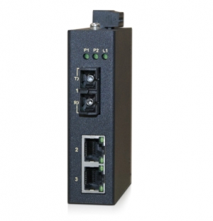
10/100M Industrial Media Converter New!
|
ETHERNET |
|
|
Supporting standards |
IEEE802.3 10Base-T, 100Base-T |
|
Data Rate |
10/100Mbps auto-sensing, Full Duplex or Half Duplex |
|
Physical Interface |
RJ45, DCE interface, 2 ports |
|
OPTICAL |
|
|
Number of Fibers |
2 or 1 |
|
Wavelength |
SM:1310/1550nm MM: 850/1310nm |
|
Fiber Type |
9/125μm(SM) ,62.5/125μm(MM) |
|
Distance |
0 ~ 20km(SM),0~2km(MM) Option: 40/60/80/120km |
|
Connector Type |
ST/FC/SC |
|
GENERAL |
|
|
Operating Temperature |
-40 ~ 70˚C / -40 ~ +158ºF |
|
Relative Humidity |
0 ~ 95% non-condensing |
|
Mean Time Between Failure (MTBF) |
> 600,000hrs |
|
Power Supply Adaptors |
12~36V DC(Dual redundant power supplies) or 85~264VAC/77~300VDC(Single power supply) |
|
Enclosure Color |
Black |
|
Dimensions ( W x H x D) mm |
12~36V DC: 26 x 95x 70mm 85~264V AC:30x 115 x 88mm |
|
IP Grade |
IP40 |
|
Power Consumption |
≤ 3W |
|
Power Supply Protection |
Reverse connection, Overload |
|
Mount Way |
DIN Rail |
|
Warranty |
2 to 5 Years |
|
IEEE STANDARD |
|
|
IEEE 802.3 |
10BaseT Ethernet |
|
IEEE 802.3u |
100BaseT(X) and 100BaseFX Fast Ethernet |
|
IEEE 802.3x |
Flow Control |
|
CERTIFICATE |
|
|
EMC |
CE, FCC |
|
EMI |
FCC Part 15. CISPR(EN55022) class A |
|
EMS |
EN61000-4-2(ESD)Level 3, |
|
|
EN61000-4-3(RS)Level 3, |
|
|
EN61000-4-4(EFT)Level 3, |
|
|
EN61000-4-5(Surge)Level 3, |
|
|
EN61000-4-6(CS)Level 3, |
|
|
EN61000-4-8 |
|
Shock |
IEC60068-2-27 |
|
Freefall |
IEC60068-2-32 |
|
Vibration |
IEC60068-2-6 |
|
Green Product |
RoHS, WEEE |

2.

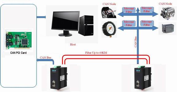
Application case:
Case Topology
Odering Information:
|
Model Number |
Description |
Fiber Mode |
Fiber Connector |
|
HFD-FO-100M-P1M |
Fiber Optic Converter,Point to Point Link,Single Fiber(BI-DI), 2km,DIN Rail Mount |
Multi Mode |
ST/SC/FC |
|
HFD-FO-100M-P1S |
Fiber Optic Converter,Point to Point Link, Single Fiber(BI-DI), 20km,DIN Rail Mount |
Single Mode |
ST/SC/FC |
|
HFD-FO-100M2-P1M |
Fiber Optic Converter,Point to Point Link,Single Fiber(BI-DI), 2km,DIN Rail Mount |
Multi Mode |
ST/SC/FC |
|
HFD-FO-100M2-P1S |
Fiber Optic Converter,Point to Point Link, Single Fiber(BI-DI), 20km,DIN Rail Mount |
Single Mode |
ST/SC/FC |
|
HFD-FO-100M-P2M |
Fiber Optic Converter,Point to Point Link,Dual Fiber(BI-DI), 2km |
Multi Mode |
ST/SC/FC |
|
HFD-FO-100M-P2S |
Fiber Optic Converter,Point to Point Link,Dual Fiber, 20km |
Single Mode |
ST/SC/FC |
|
HFD-FO-100M2-P2M |
Fiber Optic Converter,Point to Point Link,Dual Fiber(BI-DI), 2km |
Multi Mode |
ST/SC/FC |
|
HFD-FO-100M2-P2S |
Fiber Optic Converter,Point to Point Link,Dual Fiber, 20km |
Single Mode |
ST/SC/FC |
CAN to Ethernet Converter ready for Qatar Campus Elevator Automation System
CAN to Ethernet Converter(CANET-I) ready for Qatar Campus Elevator Automation System

BE's HFD-FO-CAN-P1S CAN FO Converter in US Elevator Project
BE's HFD-FO-CAN-P1S CAN Bus Fiber Converter in US Elevator Project

BE's Industrial Ethernet Switch and GPS Time Servers Installed in Vietnam Substation Automation System
BE's Industrial Ethernet Switch and GPS Time Servers Installed in Vietnam Substation Automation System(SAS). Powered up by BE's products, the SAS successfully communicated with the whole power grid communication system.

B E's Profibus Fiber Optic Converter Passed Testing in European Subway Pilot Project
B E's Profibus Fiber Optic Converter with dual redundant ring has passed the subways project testing in east Europe. The maximum total length of each ring is 1km and the maximum distance between two OLM(Profibus fiber optic converter) is 200m. The OLMs are connected to the Siemens S700 PLC. There are 10 subway stations in total, in one station there is a Profibus ring network. BE's OLM can help the project save much budget.
CANbus Over Fiber Optical Converter
CANbus Over Fiber Optical Converter(New Technology)
Model: FO-FIB-100PT-P2S/P2M
Description:
The CAN Bus series products provide an optical point-to-point or bus network connection for CAN bus data interfaces on one or two, multi mode or single mode optical fibers. The CAN Bus Point-to-Point Transmission units operate as the end or terminal points and provide an electrical connection and a two fiber optical connection. The units support CAN 1.0 and CAN 2.0 CAN standards, and Device Net. And are transparent to all high level protocols.It adopts the latest technology in the world,it can be transmitted to 20Km when it's at the baud rate of 1MB(6500 frames).
Product Features
- Up to 1Mbps data rate(Support high rate and long distance transmission)
- Baud rate Configurable,by software and rotary button
- Multimode and singlemode
- Single fiber solution
- Anti-stream: 1000 frames
- Wall mount, rack or chassis configurations
| Data | |
| Data Formats | CAN1.0 ,CAN2.0 , Device Net |
| CAN Data Rate | 0-1Mbps |
| Bit Error Rate | <1 x 10-12 |
| Connectors | |
| Data | Screw Block Terminal |
| Fiber | ST, SC or FC (ST fitted as standard) |
| Environmental | |
| Operating Temperat ure | - 3 0 C--- +70 C |
| Storage Temperature | - 40 C--- +85 C |
| Operating Humidity | 0- 95% |
| MTBF | >100,000 Hours |
| Optical | |
| Fiber | Multi mode or single mode |
| Wavelength | MM: 850nm, SM: 1310nm |
| Number of fibers | 2 or 1 |
| POWER | |
| Power Input | +9 to +40V DC |
| Mechanical | |
| Dimensions | 156(W)×108(D)×33.6(H )mm Wall Mount & DIN Rail |
|
Model Number |
Description |
Port No. |
Fiber Mode |
Fiber Connector |
|
HFD-FO-CAN-P1M |
Fiber Optic Converter,Point to Point Link, Single Fiber(BI-DI), 2km,DIN Rail Mount |
1 CAN +1 FO |
Multi Mode |
ST/SC/FC |
|
HFD-FO-CAN-P2M |
Fiber Optic Converter,Point to Point Link, Dual Fiber, 2km,DIN Rail Mount |
1 CAN+1TX+1RX |
Multi Mode |
ST/SC/FC |
|
HFD-FO-CAN-P1S |
Fiber Optic Converter,Point to Point Link, Single Fiber(BI-DI), 20km |
1 CAN +1 FO |
Single Mode |
ST/SC/FC |
|
HFD-FO-CAN-P2S |
Fiber Optic Converter,Point to Point Link, Dual Fiber, 20km |
1 CAN+1TX+1RX |
Single Mode |
ST/SC/FC |
|
HFD-FO-CAN-M2M |
Fiber Optic Converter,Multi-drop Link, Dual Fiber(BI-DI), 2km |
1 CAN+2FO |
Multi Mode |
ST/SC/FC |
|
HFD-FO-CAN-M4M |
Fiber Optic Converter,Multi-drop Link, 4 Fiber, 2km |
1 CAN+2TX+2RX |
Multi Mode |
ST/SC/FC |
|
HFD-FO-CAN-M2S |
Fiber Optic Converter,Multi-drop Link, Dual Fiber(BI-DI), 20km |
1 CAN+2FO |
Single Mode |
ST/SC/FC |
|
HFD-FO-CAN-M4S |
Fiber Optic Converter,Multi-drop Link, 4 Fiber, 20km |
1 CAN+2TX+2RX |
Single Mode |
ST/SC/FC |
|
FO-FIB-100PT |
Configurable Fiber Optic Converter, Point to Point Link,Wall Mount |
1CAN+1TX+1RX |
Single Mode MultiMode |
ST/SC/FC |
|
FO-FIB-100BT |
Configurable Fiber Optic Converter, Multi Drop Link,Wall Mount |
1CAN+2TX+2RX |
Single Mode |
ST/SC/FC |
|
FO-FIB-MIXED |
Configurable CAN Fiber Optic Switch, Point to point,Multi-drop,Star,Tree, Wall Mount |
2 CAN+2TX+2RX |
Single Mode |
ST/SC/FC |
|
SW-400T |
4 Port Configurable CAN BUS Switch, Wall Mount |
4 CAN |
|
|
|
BRIGE-200T |
Configurable CAN TO CAN Bridge |
2 CAN |
|
|
|
CANET-I |
1 Port CAN to Ethernet Converter |
1 CAN+1 TCP |
|
|
|
CANET-II |
2 Port CAN to Ethernet Converter |
2 CAN+1 TCP |
|
|
|
CAN-USB-I |
1 Port CAN to USB Converter |
1 CAN+1 USB |
|
|
|
CAN-USB-II |
2 Port CAN to USB Converter |
2 CAN+1 USB |
|
|
|
CAN-PCI-5001 |
1 Port CAN PCI Card |
1 CAN+1 PCI |
|
|
|
CAN-PCI-5002 |
2 Port CAN PCI Card |
2 CAN+1 PCI |
|
|
|
CAN-232 |
CAN to RS-232 Converter |
1 CAN+1RS232 |
|
|
|
CAN-485 |
CAN to RS-485 Converter |
1 CAN+1RS485 |
|
|
Industrial Ethernet, Ready for Industry 4.0
One of the overriding aspects of industrial networking that becomes clear when viewed over the past three decades is the pace of change that’s taken place. The speed at which updates in technology now propagate throughout the marketplace is vastly quicker than ever before. Standards are also playing a part, sometimes following, sometimes leading change.
Hence, with industrial Ethernet having now overtaken traditional fieldbus technologies in terms of the number of new nodes being installed, and influences such as Industry 4.0 having a profound impact on development, how well is industrial Ethernet suited to the demands of industrial network communication going forward?
The CLPA Gigabit white paper considers the technical aspects of industrial Ethernet technology and its variations, and their suitability to the demands of current and future application scenarios.
The impetus for change
The classic model for the spread of any given technology—i.e., innovation, early adoption, proliferation, consolidation, standardization and replacement—remains relevant, but there are also sweeping changes being wrought here by outside influences disrupting the usual sequence of events.
Industry 4.0 is a case in point in how change is being driven from a conceptual standpoint. The practical challenges driven by Industry 4.0 include cross-platform integration, Big Data and the burgeoning proliferation of artificial intelligence (AI), all of which are significant external forces affecting network technology development.
The proliferation of Ethernet in industrial control network applications has been very swift compared with the adoption and consolidation of fieldbus, and it is still in progress. There is no doubt that the open nature of Ethernet as a technology is also fueling already furious development schedules. Logic dictates that we should expect equally swift consolidation and standardization to soon follow.
The speed of all this change means that, as we embark on the journey to Industry 4.0, businesses need to carefully consider how to build their industrial communications infrastructure in order to remain competitive and thrive.
While industrial Ethernet networks can help future-proof your systems, the overall performance of these networks can also determine the success or failure of an enterprise. Industry 4.0 and the Industrial Internet of Things (IIoT) demand seamless interconnection from the smallest sensor up to enterprise-level systems and beyond. Thus, the future depicted by these concepts is going to be built on data, and lots of it. This unprecedented volume of data can provide an actionable insight into the manufacturing processes. Therefore, the speed of data management capabilities of your network will be critically important.
The automation networking landscape
To succeed with all the data delivered by Industry 4.0, it is necessary to make the best use of the data without crippling the very communications systems being used to transmit it.
We might not know exactly what these future communications infrastructures will look like, but we can already see some clues in cloud computing. We will soon see the likes of virtual programmable logic controllers (PLCs) and virtual supervisory control and data acquisition (SCADA) in the cloud, collecting data from and sending it to plant floor devices in real time.
Therefore, industrial Ethernet networks are likely to remain a mainstay in industrial communications, helping to control industry, infrastructure and utilities by connecting different devices, machines, systems and users, regardless of where they are.
Not all industrial Ethernet networks are equivalent, however.
The transfer of data can vary greatly among the various Ethernet solutions available. As a result, their performance influences their ability to handle current and future data sharing needs. Whatever network and system performance we might believe to be adequate for today’s requirements, in the future we are going to need much more of it.
To help you make decisions around how to futureproof your industrial Ethernet network, the CLPA Gigabit white paper explains the properties that affect data transfer on industrial Ethernet networks. In addition, it looks at the design of CC-Link IE Field, how it compares with other solutions, and how this technology addresses the specific requirements of Industry 4.0.