Sidebar
News Press

Administrator
Hannover MESSE-The Witness of Industry 4.0
"This year's HANNOVER MESSE has resoundingly shown that Industry 4.0 is already making a contribution to profitability," said Dr. Heinrich Frontzek, Chairman of the HANNOVER MESSE Exhibitor Committee. Exhibitors presented more than 500 showcases at the fair. "This year's lead theme of ‘Integrated Industry – Creating Value' accurately reflected the thrust of conversations at the exhibitors' stands. Rather than talking about ‘if' and ‘when,' the focus was on real investments for projects aimed at generating real benefit," said Frontzek.
HANNOVER MESSE as a nucleus for future added value
"The world of industry is looking for orientation. It's not just a matter of new products; we're talking sweeping changes affecting the entire value-adding chain. HANNOVER MESSE gives you the big picture and shows how new technologies are redefining the system," said Frontzek. More than 70% of the firms represented at this year's show were exhibiting innovations and enhancements.
Exhibitors rate the event as a solid success
Exhibitors were pleased with the run of the show, citing the high caliber of its attending professionals, the number of business talks held and the overall promotional impact of their exhibition showcases. This adds up to upbeat expectations with regard to post-show business. "The top decision-makers come to HANNOVER MESSE to find out not only about individual products, but also about complete system solutions. The show once again impressively underscored this," remarked Frontzek.
Exhibitors highly optimistic about 2017
Companies continue to be optimistic about the road ahead, with more than 70% of participating exhibitors rating the overall business climate in their sector as good to excellent. Their own prospects were seen in an even more positive light, with 80% of all exhibitors stating them as ‘good' or ‘excellent,' while 71% anticipate a further brightening of the general economic climate in the course of 2017. Accordingly, 41% of exhibitors in Germany are planning to hire more staff.
ISO 11898 standard
Since 1992, The CAN data link layer and the CAN high-speed physical layer have been standardized internationally in ISO 11898. In the beginning, the standard was published in a monolithic document, but in 2003 it was divided into several parts:
Part 1 standardized the CAN data link layer protocol and partly the physical layer (especially the bit-timing);
Part 2 specified the electric voltage level on the bus-lines for transmission speeds up to 1 Mbit/s; it also includes some system design recommendations;
Part 3 defined the electric voltage levels on the bus-lines for fault-tolerant, low-power transmissions up to 125 kbit/s;
Part 4 standardized the time-triggered CAN (TTCAN) protocol;
Part 5 added low-power functionality to the ISO 11898-2 compliant transceivers;
Part 6 specified the selective wake-up functionality for high-speed transceivers.
The second edition of ISO 11898-1, published in 2015, comprises the definitions of the Classical CAN protocol as standardized in ISO 11898-1:2003 and the CAN FD protocol, which specifies two bit-rates and payloads up to 64 byte. 2016, the second edition of ISO 11898-2 was published. It substitutes the previous versions of part 2, part 5, and part 6. It specifies the transceiver characteristics for bit-rates up to 5 Mbit/s.
Additionally, ISO has developed conformance test plans for ISO 11898-1 and ISO 11898-2 implementations. The corresponding standards are ISO 16845-1, which was published 2016 and ISO 16845-2, which will be published soon.
How to Select Most Suitable Fiber Optic?
1 Fiber Optic's Type
More than 1.1 multimode fiber optic multimode fiber is the optical fiber that can transmit multiple optical conduction modes. At the beginning of the optical fiber communication, is the use of multimode fiber (g. 651 fiber), the working wavelength at 850 nm and 1300 nm, the attenuation constant of the < 4 db/km respectively and < 3 db/km, the dispersion coefficient of < 120 ps/respectively (nm) km) and < 6 ps/(nm) km). Due to its attenuation and dispersion, it can only be used for short distance communication. However, it has a large diameter and is not high enough for connectors and connectors. It is easier to use than single-mode fiber and is currently used in computer networks.
A single mode fiber optic single mode fiber is the optical fiber that transmits only one optical conduction module (schema). Its main advantage is that the attenuation is small, the transmission is long, the transmission capacity is large, and it is widely used in the long distance backbone network, the metropolitan area network, the connecting network and so on. Single-mode fiber due to transmit only base model, it does not exist delay difference between mold, with much larger bandwidth than multi mode fiber, the bandwidth of the single-mode fiber can reach more than dozens of GHz. So single mode fiber is especially suitable for long-distance, high-volume communication systems. With the development of optical fiber manufacturing technology and communication technology, the type of single-mode fiber is also developing.

Common single-mode fiber is the following:
The 1.2.1 g. 652 fibre-optic g. 652 fiber optic cable is a regular optical fiber, and it has both 1310 nm and 1550nm Windows. The zero dispersion point is located in the 1310nm window, while the minimum attenuation is in the 1550nm window. The typical values of the two Windows are: 1310 nm window attenuation is 0.3 ~ 0.4 dB/km, the dispersion coefficient of 0 ~ 3.5 ps/(nm) km), 1550 - nm window of attenuation is 0.19 ~ 0.25 dB/km, dispersion coefficient is 15 ~ 20 ps/(nm) km).
The 1.2.2 G. 653 optical fiber g. 653 optical fiber is the dispersion-shifted fiber, and is called the optimal optical fiber for the 1550nm window. People through the optical refraction profile design, to move the zero dispersion point to a 1550 - nm window, with the minimum of the fiber attenuation window with matches, make 1550 nm window has a minimum at the same time the dispersion and the minimum decay. The typical value of its 1550nm window is: the attenuation coefficient is 0.19 ~ 0.25 dB/km, the zero dispersion point is in 1525 ~ 1575nm wavelength area, and the dispersion coefficient of this interval is < 3.5 ps/(nm. Km). The excellent properties of this optical fiber in the 1550nm window make it the best choice for single wavelength, large capacity, and long distance transmission. If the TDM system is expanded purely along the way, the 20Gbit/s system can be launched directly without any dispersion compensation. The important defect of the g. 653 fiber is that the four-wave mixing limit is restricted by the use of the waveform multiplexing (WDM). So-called four-wave mixing phenomenon is caused by the nonlinear of the fiber, when different wavelengths in a single fiber transmission at the same time, due to the interaction, can produce new and, difference of wave component.
1.2.3 g. 655 optical fiber g. 655 optical fiber or non-zero dispersion-shifted fiber, it is in order to solve the g. 653 optical fiber in serious four-wave mixing effect, of g. 653 optical fiber the zero dispersion point of the move, to keep the dispersion coefficient of 1540 ~ 1565 nm range from 1.0 ~ 4.0 ps/(nm) km), avoiding the zero dispersion area, maintain a dispersion value, at least in order to more convenient to open multiple wavelength WDM systems. In the properties of the g. 655 fiber, the other features are the same as the G. 653, except for the zero dispersion point. It has a minimum attenuation coefficient and dispersion coefficient in the 1550nm window. Although its dispersion coefficient is slightly greater than G. 653 fiber, it has greatly reduced the dispersion limit distance relative to g. 652 fiber. It successfully solved the disadvantages of the g.652 fiber optic dispersion and g. 653 fiber in the 1550nm wavelength region, and the advantages of these two fibers. It can open a high speed 10Gbit/s, 20Gbit/s TDM system, and it can also be expanded by WDM mode.

Ways to increase the capacity of optical fiber transmission
In theory, increase the transmission capacity can have the following several ways: air separation of multiplexing (SDM), the electric time-division multiplexing (TDM), wavelength division multiplexing (WDM) and optical frequency division multiplexing (FDM) O, optical time-division multiplexing (TDM) O technology and optical soliton (So liton). Based on the practicality, only the TDM and WDM are briefly introduced.
TDM technology (TDM) TDM technology is a technique that is used to multiplex signals and is a traditional method of ampliation. PDH's 34,140, 565 Mbit/s, and the SDH's 155,622,2488,9952 Mbit/s are all used for reuse on electrical signals. According to the statistics, at 215Gbit/s, the price per bit of the system is reduced by about 30 percent per bit. That's why, in the past, people started using TDM technology. With the improvement of reuse rate, for example reaches 10 gbit/s is close to the limit of the silicon and the technology of arsenic, don't have much potential, the effect of fiber dispersion is also more serious, to put forward higher requirements to optical fiber. 2.2 wavelength division multiplexing (WDM) technology by WDM technology is to make full use of the single mode fiber low loss area has the huge bandwidth resources (about 25 THZ), USES the wavelength division multiplexer (wave) to different rules in the sender will wavelength of the signal light transmitted carrier and combined into a single fiber. At the receiving end, a wave separator (splitter) separates the light carriers that carry different signals from different wavelengths.
WDM technology of the main features are: (1) can make full use of optical fiber huge bandwidth resource, make a single fiber transmission capacity than single wavelength transmission increases several times or more. The use of N wavelengths to be transmitted in single mode fiber, which can be used to save the fiber in large volumes. (3) because of the same optical fiber transmission signal wavelength independent of each other, thus it can be completely different signal transmission properties, complete various business signal synthesis and separation, including digital signal and analog signal, synthesis and separation of the SDH and PDH signals. The channel is transparent to the data format, which is independent of the signal speed and the mode of modulation, which is the ideal method for network expansion and development. The use of WDM technology is used to enable network exchange and recovery to enable transparent, highly survivable optical networks in the future.
Suggestions for selecting fibre correctly
Choice must consider three key parameters of optical fiber types: (1) the biggest WuZhongJi each wavelength of the maximum bitrate transmission distance (2) (3) each number of the wavelength of the fiber. Of course, all these parameters should consider the requirements of the optical fiber final phase, not the initial requirements. According to the above parameters, if the maximum WuZhongJi transmission distance in 50 ~ 100 km (depending on the types of laser), then the g. 652 conventional fiber because of its low price is a more appropriate choice. If the distance is longer, and each wavelength of maximum bit rate is less than 10 gbit/s, so should be preferred to conventional optical fiber. If the distance is long, but only need single wavelength high rate (more than 10 gbit/s), then can choose g. 653 dispersion-shifted fiber. If the distance is long and requires a multi-wavelength load of 10 Gbit/s or higher speed, the g. 655 non-zero-dispersion-shifted fiber is the best option.
Thus put forward the following optical fiber selection principles: (1) short trunk optical cable access network and fiber because the distance is short, use more fiber core to increase the investment is not big, therefore generally should choose g. 652 conventional optical fiber. (2) the long-distance optical cable for long transmission distance, using more fiber core investment increase, so must have a high rate and multiple wavelengths of WDM technology, priority should be given by g. 655 dispersion-shifted fiber.
It is reported that in recent years in North America are starting a new round of fiber laying a climax, but on the trunk line has stopped using g. 652 optical fiber, but all adopt the g. 655 non-zero dispersion-shifted fiber. This trend deserves attention.
Whether choose g. 652 optical fiber or g. 655 optical fiber, in addition to conventional index for the attenuation and dispersion of the fiber and other request, generally can be put forward according to the requirement of the transmission rate of 10 gbit/s, PMD parameters, thus for later use WDM means to rapidly expand the capacity of the transmission system.
CAN to Fiber Optic Router Made by BE Plays a Role in Substation Automation System in Europe
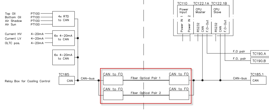
CAN to Fiber Optic Router Made by BE Plays a Role in Substation Automation System in Europe. The product made by BE(Bueno Electric) works mainly as the router in this SAS system, the router has 6500 frames/second buffer/second and the buffer can be removed automatically in the nominated time to avoid the data jam. The router supports multi ways of communication such as star,tree,multi-drop bus and so on.
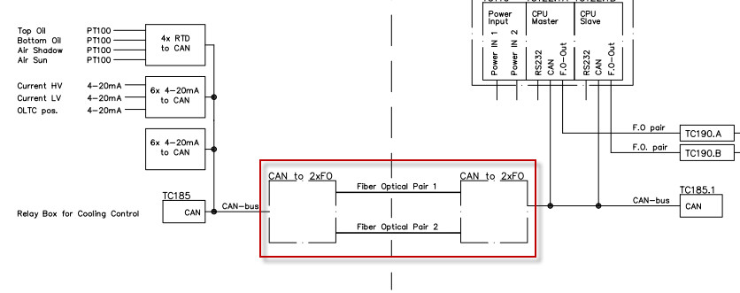
BE's CAN Bus Fiber Optic Switch with 2 CAN and 2 Optical Ports in ABB's Projects
BE's CAN Bus Fiber Optic Switch with 2 CAN and 2 Optical Ports Installed in ABB's Power Automation Projects. The ABB needs 2 channels of CAN to Fiber Optic in one converter, one channel is as normal communication and the other channel works as redundancy, only when channel 1 CAN is broken, the channel 2 CAN starts to work to maintain the safety of the whole system. In the world wide market,there is no such product yet, so BE designed this model for ABB. The model of CAN Bus to fiber optic switch has 2 CAN and 2 fiber optic ports, this model has redundancy or router function. Any one port among the 4 ports can communicate with each other or with defined port,this provides a quite flexible option for customers.
Please see the figure of this project case as the below:
What is POE(power over Ethernet)?
Power over Ethernet (PoE) technology enables ordinary Ethernet network cables to function as power cords. In a PoE-enabled network, direct electrical current (DC) flows over the network cable together with normal Ethernet data traffic. Most PoE devices follow either IEEE standard 802.3af or 802.3at.
Power over Ethernet was designed for use with portable and wireless electronic equipment like Wi-Fi access points (APs), webcams, and VoIP phones.
PoE allows network devices to be installed in ceilings or wall spaces where electric outlets are not within easy reach.
A technology unrelated to PoE, Ethernet over power lines enables ordinary electric power lines to act as long-distance Ethernet network links.
Why Most Home Networks Don't Use PoE
Because homes typically have many power outlets and relatively few Ethernet wall jacks, and many consumer gadgets use Wi-Fi connections instead of Ethernet, the applications of PoE for home networking are limited. Network vendors typically only include PoE support on their high-end and business-class routers and network switches for this reason.
DIY consumers can add PoE support to an Ethernet connection using a relatively small and cheap device called a PoE injector. These devices feature Ethernet ports (and a power adapter) that enable standard Ethernet cables with power.

What Kinds of Equipment Work with PoE?
The amount of power (in watts) that can be supplied over Ethernet is limited by the technology.
The exact threshold of power needed depends on the rated wattage of the PoE source and the power draw of the client devices. IEEE 802.3af, for example, guarantees only 12.95W of power on a given connection. Desktop PCs and laptops generally cannot operate over PoE due to their higher power needs (typically 15W and up), but portable devices like webcams that function at less than 10W can.
Business networks sometimes incorporate a PoE switch through which a group of webcams or similar devices operate.
How does the CAN bus receives the Filter
CAN bus in the data frame is sent on the bus, the other CAN controller is through acceptance filtering to determine whether the data on the bus frame ID and this node is consistent, if accord with this node, then the data on the bus were deposited in the bus controller in the corresponding register, or abandon the data, thus able to lighten the load of the bus controller. In other words, the bus data frame ID through after receiving node acceptance filtering is consistent, can be accepted.
Then, bus controller is how to carry out the acceptance filtering? Acceptance filtering points single filter and double filtering. Standard frame and extended frame because ID length is different, the two kinds of filter also differ.
Extended frame double filtering method
The so-called double filtering, is twice the filtering, but not two filter will need only double pass through, two filter as long as there is a successful pass, then the default filtering can receive data.
As shown in the table above, ACR is receiving code registers, AMR is receiving mask register. ACR is generally need to be in conformity with the corresponding ID, but if on the corresponding bit of AMR is set to 1, the ID of the data can not AMR corresponding place, also is to have the effect of shielding.
For example. If ACR0 = 11101111, AMR0 = 00000000, so want to through the acceptance filtering, must be ID. 28 - ID. 21 = ACR0 = 11101111. If AMR0 = 00010000, then ID. 28 - ID. 21 = 11111111, also can through the acceptance filtering, as the fifth AMR0 is 1, which is blocked ACR0 fifth. So ID corresponding bit can not ACR0 consistent.
Under the double filtering method of extending the frame, ACR0 \ ACR1 corresponding ID. 28 - ID. 13, ACR2 \ ACR3 also respectively corresponding to the ID. 28 - ID. 13, it achieved the effect of the two filter.
Life Span of Industrial Fiber Optic Converters
As contact with the personnel of optical fiber communication, to the service life of the optical transceiver is concerned about. How long is the service life of it?
Industrial-grade fiber optic converter as important optical fiber transmission equipment, in industrial grade fiber optic converter design, the choice of components of nations, it decides the performance of the product, life and cost. Its service life is mainly related to it of light module, the service life of the general in five years. Fiber optic transceivers use for a long time, five years of its main components light module because loss is too big, laser damage and cannot work normally.
Optical transceiver is generally used in Ethernet cable can't cover, optical fiber must be used to extend the transmission distance of actual network environment, at the same time help the last kilometer in the fiber optic lines connected to the man and the outer also played a big role in the network. So we need to choose when the choice products of good quality, stable industrial fiber optic transceivers.
CAN Termination Resistors-Vital Part
CAN bus terminal resistance, just as its name implies is the resistance of the end of the bus. The resistance is small, but in the CAN bus communication has an important role.

The role of terminal resistance
There are two: the role of CAN bus terminal resistance
A, improve the anti-interference ability, ensure that the bus into the recessive state quickly.
Second, improve the quality of the signal.
Improve the ability of anti-jamming
CAN bus has the "dominant" and "hidden" two states, "the dominant" represents "0", "1", "hidden" representative is decided by the CAN transceiver. Figure 1 is a typical internal structure, the CAN transceiver CANH, CANL bus connection.
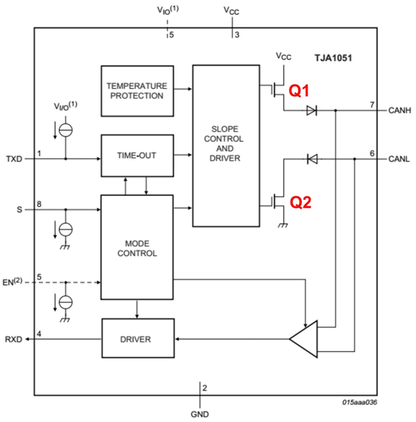
Figure 1
Bus is dominant, the transceiver inside Q1 and Q2 conduction, produce pressure difference between CANH, CANL; Implicit, Q1 and Q2 as CANH, CANL in a passive state, differential pressure of 0.
If the bus without load, implicit differential resistance tolerance is very big, when the external interference only need minimal energy can make the bus into the dominant (generally the transceiver of dominant minimum threshold voltage is only 500 mv). To improve the anti-interference ability of the bus when the hidden, you can add a difference load resistance, and resistance as small as possible, in order to put an end to most of the noise energy. However, excessive current bus in order to avoid the need to enter, dominant resistance nor too small.
To ensure fast into the recessive state
During the dominant status of the bus parasitic capacitance can be charging, and in return to the recessive state, the capacitor to discharge. If CANH, CANL didn't put any resistance load, between capacitance only through differential resistance discharge within the transceiver. We between transceivers CANH, CANL join simulated experiment, the capacitance of a 220 pf bit rate of 500 kbit/s, waveform as shown in figure 2, figure 3.
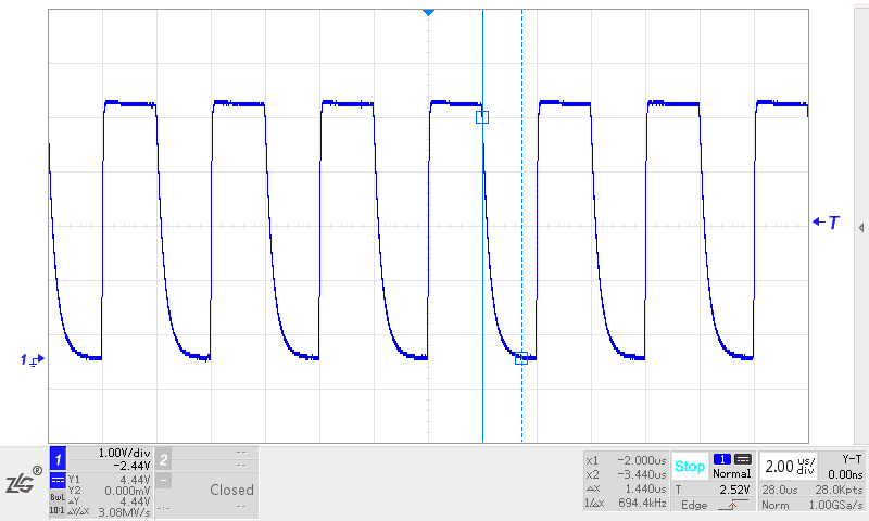
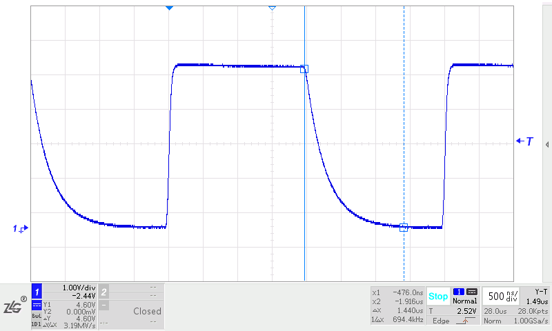
Figure 3
See from figure 3, the time of dominant to recessive 1.44 mu S, in the case of high sampling points can barely communication, if the communication rate higher, or more parasitic capacitance, it is hard to ensure the normal order of the communication.
In order to let the bus parasitic capacitance discharge rapidly, ensure that the bus into the recessive state quickly, need in CANH, CANL placed between a load resistor. After a 60 Ω resistance increase, waveform as shown in figure 4, figure 5. See from the table, the dominant to recessive time down to 128 ns, and explicit build time.
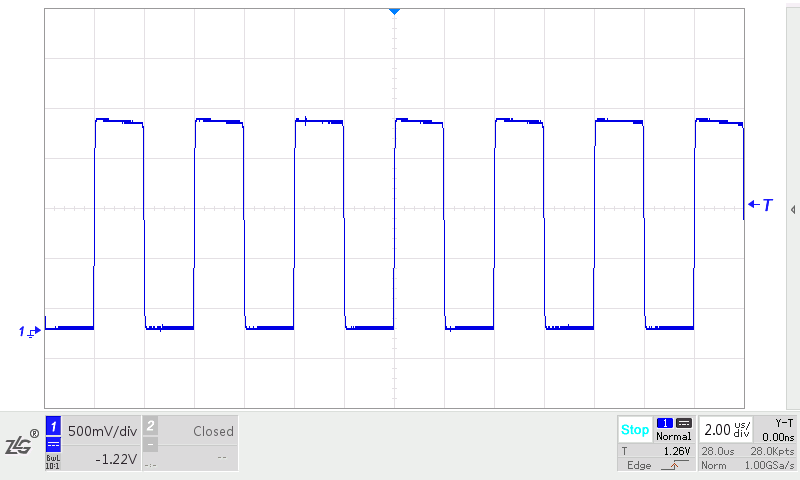
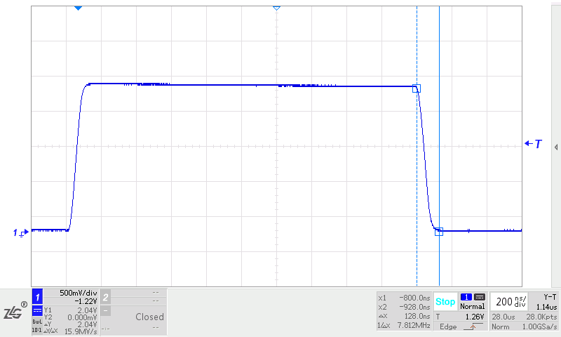
Figure 5
Improve the quality of the signal
Signals under the condition of high conversion rate, edge energy meet impedance mismatch, produces the signal reflection; Transmission cable cross section geometric structure changes, the characteristics of the cable impedance changes, also can cause reflection.
At the end of the bus cable, rapid changes in impedance leads to the edge of signal energy reflection, bus signal will produce ringing, if ringing range is too big, can affect the communication quality. Increase in the end of the cable a characteristic impedance consistent with cable terminal resistance, it can be part of the energy absorption, avoid the generation of ringing.
We conducted a simulation experiment, the bit rate is 1 mbit/s, transceiver CANH, CANL pick up a piece of about 10 m twisted-pair, transceiver 120 Ω termination resistor assurance implicit conversion time, end without load. The end of the signal waveform is shown in figure 6, signal rise along the ringing.
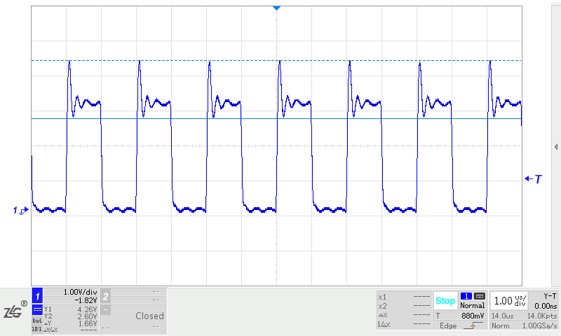
Figure 6.
If add a twisted-pair cable end 120 Ω resistance, terminal signal waveform, ringing disappeared, as shown in figure 7.
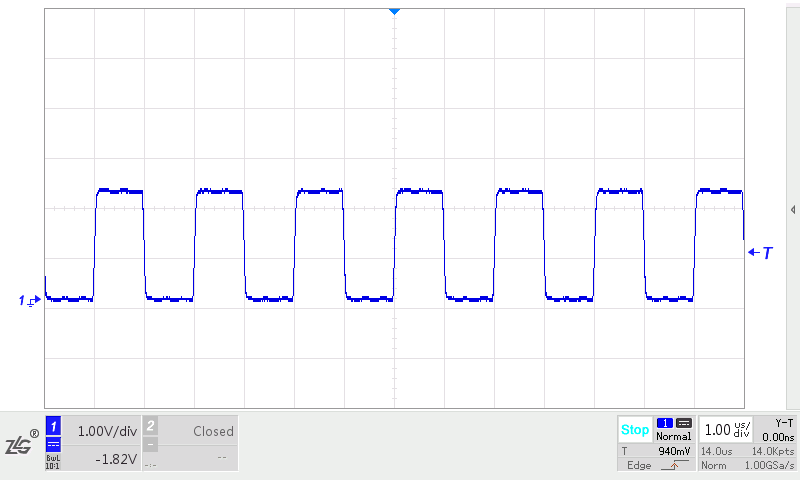
Figure 7.
Generally in the linear topological, is sending end on both ends of the cable, and the receiver, so the cable ends need to add a resistor.
Why choose 120 Ω
Any cable for the characteristic impedance can be obtained by means of experiment. One end of the cable connect the wave generator, the other end to an adjustable resistance, and resistance were observed by oscilloscope waveform. Adjust the size of the resistance tolerance, until the signal on the resistance is a good without ringing in the square wave, the resistance can be thought of in accordance with the characteristics of the cable impedance.
Most of the auto cables are single. If you use two cars using typical cables, they are made of twisted pair, is a characteristic impedance CAN be obtained in accordance with the above method is about 120 Ω, this also is CAN standards recommended by the terminal resistance tolerance.
CAN Bus signal Analysis in the Subways
Railway, metro vehicles has wide use of CAN bus communication. Using its good real-time and error correction ability, improve the control efficiency and reliability of vehicle parts. But in metro operation, some lines will appear accidental CAN poor communications, node drop-off.
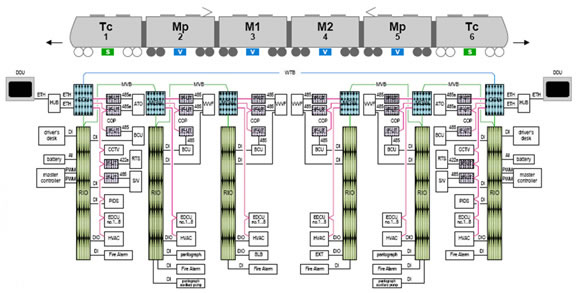
Field bus topology, as shown in figure 2, marshalling of metro vehicle for 6 section, where we test points in the air conditioning controller CAN interface position, the main test signal the CAN bus communication quality.
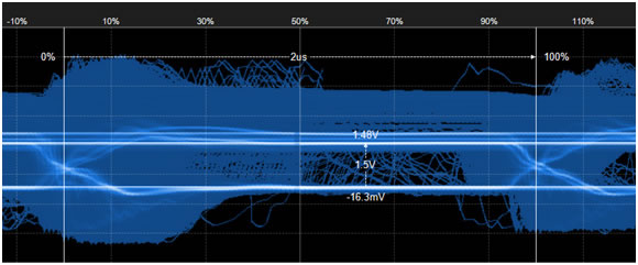
By eye diagram time measurement, the entire waveform doing eye diagram, measurement results visible waveform edge too slowly, a portion of the waveform is rising along with larger ringing, falling edge have bigger play phenomenon, that the bus has a discrete part of the signal. Difference level amplitude is less than the standard of 2.0 1.5 V V ISO11898-2 standard
1. The air conditioning of waveform analysis
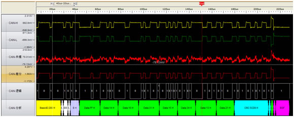
From air conditioning CAN frames with ID: 0 x331, x332 0, 0 x333, select one of the ID 0 x331 message, waveform as shown in figure 4. Visible difference level have obvious phenomenon of "play".
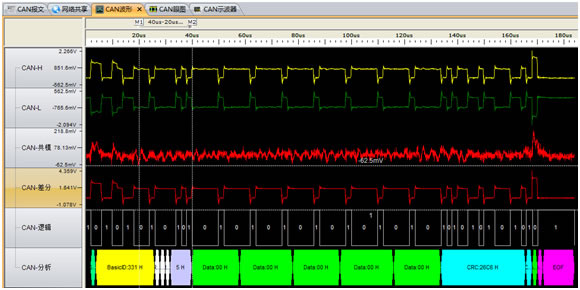
The ID 0 x331, 0 x332, 0 x333 frame waveform doing eye diagram, as shown in figure 5. CAN clearly see the CAN waveform amplitude is 1.5 V (those with high amplitude and other frame is raised when the arbitration).
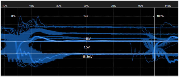
Steep analysis: CAN the differential waveform edge, the edge is clear, but the amplitude is 1.5 V, CAN than the standard difference level (at two ends of the euro 120 resistance) of 2.0 V to 0.5 V, the less there are two possible:
CANH on (1) the CAN interface and CANL may resistance of each series by about 10 euro 120 with two parallel partial pressure, to make the actual waveform is only 1.5 V. 1, with a power amplifier circuit, and through can make the control of its work;
(2) the network terminal resistance more added 1 euro 120, three 120 bus is what is the resistance, leading to reduced to 1.5 V voltage amplitude.
Look from the waveform, and obvious phenomenon of "play", air conditioning CAN interface position impedance discontinuity. , although its position is the actual terminal terminal resistance is not in it, or its position to the end of the long branches.
2. CAN master the waveform
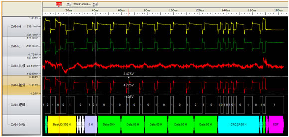
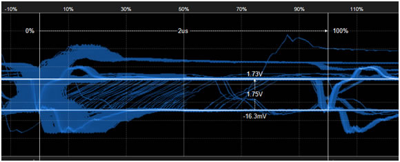
CAN master the CAN frame ID 0 x200, 0 x231. Select one of the ID 0 x200 message, waveform is shown in figure 6
The ID 0 x200, 0 x231 frame waveform doing eye diagram, as shown in figure 7. CAN be clearly seen from the CAN from the master CAN wave reaches the air conditioning CAN interface of amplitude is 1.8 V (measurement point in the network card side, those with high amplitude and other frame is raised when the arbitration). Along with rising and falling waveform resides.
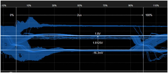
Analysis: the test points to measure the difference level of amplitude is 1.8 V, is less than the standard 2.0 V, 0.2 V, may be CAN master in CANH and CANL also series resistance, or the transmission wires, joint has certain pressure drop.
CAN increase along the slow suggests differential waveform from CAN master interface to the air conditioning CAN lead impedance is larger. Falling edge with corrugated reside, but also for its position is the actual terminal air conditioner CAN interface, but terminal resistance is not in it, or its position to the end of the long branches.
3. The actual connect resistor location of the node
The eye is done in the diagram as shown in figure 9.
Analysis: through the eye chart, its decline along a steep drop to zero, but then "bullet", explain the terminal resistance was installed above, but it is not the actual terminal, and from the actual terminal reflected wave, leading to "play".
From what has been discussed above
(1) of the system CAN wave exists serious phenomenon of "play", has lead to the risk of errors. Through the analysis of the front, is caused by the impedance discontinuity. Resistance and impedance discontinuity, is the bus terminal installation position error;
(2) the air conditioning CAN interface the resistance of the series is too big lead to partial pressure. Difference is only 1.5 V voltage amplitude, easy to changes in temperature, aging lines or voltage fluctuation, lead to an error or even communication can't do it. Please control series resistance not greater than 5.1 euro.
(3) transfer impedance conductor or joint is too large. Lead to rising slope too slowly, only 3.55 V/us, far less than 16 V/us standard value, easy to changes in temperature or long-term running, cause the failure of resynchronization of bit errors or mistakes, CRC check even unable to communication. Please check the transmission wire specifications, and joint resistance, ensure that the impedance is less than 0.02 euro/m (or the equivalent for the wire diameter of 1.0 was more shielded twisted-pair cable).