Sidebar
News Press

Administrator
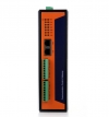
Datasheet 2015 BE-6000 Remote I/O Module
Clarification on IEC Protocol Configure Tool
Due to the development cost,Our IEC protocols configure tool software is not for free. Therefore,please first buy our product to get the configure tool software.
Our IEC gateway is based on Power PC platform,it's a heavy industrial grade embedded PC product. The configure tool software is the result of the efforts of Bueno Electric Team for years.The Configure tool support both server and client,it supports the protocols including IEC60870-5,IEC-61850,Modbus RTU,Modbus TCP.OPC,DNP3 and many other self-defined protocols.It's a quite strong software platform.
For the software, please get in touch with our sales team: This email address is being protected from spambots. You need JavaScript enabled to view it.
ABB RP570 protocol
Introduction
RP570 = ABB S.P.I.D.E.R. RTU Protocol 570
RP570 is a protocol used between an RTU (Remote Terminal Unit) in a substation and the FE (Front End), which is usually the SCADA software in the Control Centre.
RP570 was developed by ABB in beginning of 1990. It was based on IEC 57 part 5-1, presently known as IEC 60870. Known variations are RP571, ADLP80 and ADLP180.
| ISO/OSI layer | RP570 layer |
|---|---|
| 7. Application layer | Application layer |
| 6. Presentation layer | |
| 5. Session layer | |
| 4. Transport layer | Link layer |
| 3. Network layer | |
| 2. Data link layer | |
| 1. Physical layer | Physical layer |
Physical layer
Usually a RS232 (V.24) serial connection.
Link layer
Usually:
- 1 start bit
- 8 data bits
- 1 parity bit (even)
- stop bit
Fixed length frame
| Byte pos | Length | Value | Description |
|---|---|---|---|
| 0 | 1 | 0x10 | Start character |
| 1 | 1 | Address | |
| 2 | 1 | Function | |
| 3 | 1 | Checksum | |
| 4 | 1 | 0x16 | Stop character |
Variable length frame
| Byte pos | Length | Value | Description |
|---|---|---|---|
| 0 | 1 | 0x68 | Start character |
| 1 | 1 | N | Length (2-255 bytes) |
| 2 | 1 | N | Length (2-255 bytes) |
| 3 | 1 | 0x68 | Start character |
| 4 | 1 | Address | |
| 5 | 1 | Function | |
| 6 | N-2 | Data | |
| 5+N | 1 | Checksum | |
| 6+N | 1 | 0x16 | Stop character |
Application layer
To be done...
SerialMon support
- Fixed and variable length frames.
- Partial decoding of IDS, IDM, AVS, AVM, FCOM and TEV packets.
- Tracking of binary and analog blocks (addresses).
About Wireshark
Features
Wireshark has a rich feature set which includes the following:
Deep inspection of hundreds of protocols, with more being added all the time
Live capture and offline analysis
Standard three-pane packet browser
Multi-platform: Runs on Windows, Linux, OS X, Solaris, FreeBSD, NetBSD, and many others
Captured network data can be browsed via a GUI, or via the TTY-mode TShark utility
The most powerful display filters in the industry
Rich VoIP analysis
Read/write many different capture file formats: tcpdump (libpcap), Pcap NG, Catapult DCT2000, Cisco Secure IDS iplog, Microsoft Network Monitor, Network General Sniffer® (compressed and uncompressed), Sniffer® Pro, and NetXray®, Network Instruments Observer, NetScreen snoop, Novell LANalyzer, RADCOM WAN/LAN Analyzer, Shomiti/Finisar Surveyor, Tektronix K12xx, Visual Networks Visual UpTime, WildPackets EtherPeek/TokenPeek/AiroPeek, and many others
Capture files compressed with gzip can be decompressed on the fly
Live data can be read from Ethernet, IEEE 802.11, PPP/HDLC, ATM, Bluetooth, USB, Token Ring, Frame Relay, FDDI, and others (depending on your platform)
Decryption support for many protocols, including IPsec, ISAKMP, Kerberos, SNMPv3, SSL/TLS, WEP, and WPA/WPA2
Coloring rules can be applied to the packet list for quick, intuitive analysis
Output can be exported to XML, PostScript®, CSV, or plain text
Remote Terminal Unit
A remote terminal unit (RTU) is a microprocessor-controlled electronic device that interfaces objects in the physical world to a distributed control system or SCADA (supervisory control and data acquisition) system by transmitting telemetry data to a master system, and by using messages from the master supervisory system to control connected objects.[1] Another term that may be used for RTU is remote telecontrol unit.
An RTU monitors the field digital and analog parameters and transmits data to the Central Monitoring Station. It contains setup software to connect data input streams to data output streams, define communication protocols, and troubleshoot installation problems.
An RTU may consist of one complex circuit card consisting of various sections needed to do a custom fitted function or may consist of many circuit cards including CPU or processing with communications interface(s), and one or more of the following: (AI) analog input, (DI) digital input, (DO/CO) digital or control (relay) output, or (AO) analog output card(s).
Power supply
A form of power supply will be included for operation from the AC mains for various CPU, status wetting voltages and other interface cards. This may consist of AC to DC converters where operated from a station battery system.
RTUs may include a battery and charger circuitry to continue operation in event of AC power failure for critical applications where a station battery is not available.
Digital or status inputs
Most RTUs incorporate an input section or input status cards to acquire two state real world information. This is usually accomplished by using an isolated voltage or current source to sense the position of a remote contact (open or closed) at the RTU site. This contact position may represent many different devices, including electrical breakers, liquid valve positions, alarm conditions, and mechanical positions of devices.
Analog inputs
An RTU can monitor analog inputs of different types including 0-1 mA, 4–20 mA current loop, 0–10 V., ±2.5 V, ±5.0 V etc. Many RTU inputs buffer larger quantities via transducers to convert and isolate real world quantities from sensitive RTU input levels. An RTU can also receive analog data via a communication system from a master or IED (Intelligent Electronic Device) sending data values to it.
The RTU or host system translates and scales this raw data into the appropriate units such as gallons of water left, temperature degrees, or Megawatts, before presenting the data to the user via the HMI.
Digital (control) outputs
RTUs may drive high current capacity relays to a digital output (or "DO") board to switch power on and off to devices in the field. The DO board switches voltage to the coil in the relay, which closes the high current contacts, which completes the power circuit to the device.
RTU outputs may also consist of driving a sensitive logic input on an electronic PLC, or other electronic device using a sensitive 5 V input.
Analog outputs
While not as commonly used, analog outputs may be included to control devices that require varying quantities, such as graphic recording instruments (strip charts). Summed or massaged data quantities may be generated in a master SCADA system and output for display locally or remotely, wherever needed.
Software and logic control
Modern RTUs are usually capable of executing simple programs autonomously without involving the host computers of the DCS or SCADA system to simplify deployment and to provide redundancy for safety reasons. An RTU in a modern water management system will typically have code to modify its behavior when physical override switches on the RTU are toggled during maintenance by maintenance personnel. This is done for safety reasons; a miscommunication between the system operators and the maintenance personnel could cause system operators to mistakenly enable power to a water pump when it is being replaced, for example.
Maintenance personnel should have any equipment they are working on disconnected from power and locked to prevent damage and / or injury.
Communications
An RTU may be interfaced to multiple master stations and IEDs (Intelligent Electronic Device) with different communication media (usually serial (RS232, RS485, RS422) or Ethernet). An RTU may support standard protocols (Modbus, IEC 60870-5-101/103/104, DNP3, IEC 60870-6-ICCP, IEC 61850 etc.) to interface any third party software.
Data transfer may be initiated from either end using various techniques to insure synchronization with minimal data traffic. The master may poll its subordinate unit (Master to RTU or the RTU poll an IED) for changes of data on a periodic basis. Analog value changes will usually only be reported only on changes outside a set limit from the last transmitted value. Digital (status) values observe a similar technique and only transmit groups (bytes) when one included point (bit) changes. Another method used is where a subordinate unit initiates an update of data upon a predetermined change in analog or digital data. Periodic complete data transmission must be used periodically, with either method, to insure full synchronization and eliminate stale data. Most communication protocols support both methods, programmable by the installer.
Multiple RTUs or multiple IEDs may share a communications line, in a multi-drop scheme, as units are addressed uniquely and only respond to their own polls and commands.
IED communications
IED communications transfer data between the RTU and an IED. This can eliminate the need for many hardware status inputs, analog inputs, and relay outputs in the RTU. Communications are accomplished by copper or fibre optics lines. Multiple units may share communication lines.
Master communications
Master communications are usually to a larger control system in a control room or a data collection system incorporated into a larger system. Data may be moved using a copper, fibre optic or radio frequency communication system. Multiple units may share communication lines.
Comparison with other control systems
RTUs differ from programmable logic controllers (PLCs) in that RTUs are more suitable for wide geographical telemetry, often using wireless communications, while PLCs are more suitable for local area control (plants, production lines, etc.) where the system utilizes physical media for control. The IEC 61131 programming tool is more popular for use with PLCs, while RTUs often use proprietary programming tools.
RTUs, PLCs and DCS are increasingly beginning to overlap in responsibilities, and many vendors sell RTUs with PLC-like features and vice versa. The industry has standardized on the IEC 61131-3 functional block language for creating programs to run on RTUs and PLCs, although nearly all vendors also offer proprietary alternatives and associated development environments.
In addition, some vendors now supply RTUs with comprehensive functionality pre-defined, sometimes with PLC extensions and/or interfaces for configuration.
Some suppliers of RTUs have created simple graphical user interfaces GUI to enable customers to configure their RTUs easily. In some applications dataloggers are used in similar applications.
A programmable automation controller (PAC) is a compact controller that combines the features and capabilities of a PC-based control system with that of a typical PLC. PACs are deployed in SCADA systems to provide RTU and PLC functions. In many electrical substation SCADA applications, "distributed RTUs" use information processors or station computers to communicate with digital protective relays, PACS, and other devices for I/O, and communicate with the SCADA master in lieu of a traditional RTU.
Applications
##Remote monitoring of functions and instrumentation for: ##Oil and gas (offshore platforms, onshore oil wells)
##Networks of pump stations (wastewater collection, or for water supply)
##Environmental monitoring systems (pollution, air quality, emissions monitoring)
##Mine sites
##Air traffic equipment such as navigation aids (DVOR, DME, ILS and GP)
##Remote monitoring and control of functions and instrumentation for: ##Hydro-graphic (water supply, reservoirs, sewerage systems)
##Electrical power transmission networks and associated equipment
##Natural gas networks and associated equipment
##Outdoor warning sirens
Evaluation of Grid Monitoring Protocols:IEC 61850 & IEC 60870-5-104
Which is the best protocol for the monitoring and telecontrol of power grids: IEC 61850 or IEC 60870-5-104? Distribution network operators gave us the task of mapping out the pros and cons of both standards.
Power grids are becoming increasingly difficult to manage centrally using their existing supervisory control and data acquisition (SCADA) systems.
Today, SCADA systems require more interactivity. In order to continue ensuring the balance between electricity demand and supply on the grid, SCADA systems need to be able to record and transmit data from wind turbines, solar panels, electric vehicles, substations, etc. so that the appropriate control actions can be initiated whenever and wherever necessary.
Difference between IEC 61850 and IEC 104
In order to ensure such monitoring and telecontrol over TCP/IP protocols, the International Electrotechnical Commission (IEC) has developed protocol standards for electric power systems and substations.Bueno Electric examined the pros and cons of both protocols using a model of the power grid of the future including high- and medium-voltage substations, expected connection points for wind turbines and solar panels, and electric vehicle charging points designed by NARI,ABB and SAC. Our experts came to the following conclusions:
IEC 60870-5-104 is the standard for communicating standardized data from power grid substations to the grid operator. It perfectly meets operators current communication needs.
IEC 61850 is a protocol for substation automation and makes it possible to consult additional data and initiate the appropriate local actions automatically or remotely by a central operator. It opens up the possibility for more interactive, self-healing smart grids.
As IEC 61850 creates more opportunities for the future intelligent management of electric grids,Bueno Electric decided to carry out additional tests in order to evaluate the protocol’s practical use.
Along with several young start-ups that are manufacturing smart substation measurement devices, Bueno Electric developed a laboratory-scale test set-up to evaluate how well this new equipment can be integrated into the existing infrastructure. The test results provided insight into the monitoring and telecontrol possibilities.
We also evaluated the possibility of automatically initiating local control actions. For instance, we developed a wind turbine peak shaving case. We determined which parameters should be monitored and developed an algorithm that calculates the threshold values for each parameter, so that the appropriate control actions can automatically be initiated whenever and wherever necessary to ensure the local balance on the grid. The tool also sends out reports on the control actions to the central operator. In other words, the smart grid of the future is fast approaching.
We evaluated the IEC 61850 and 60870-5-104 protocols using a model that included high- and medium-voltage substations, expected connection points for wind turbines and solar panels, and electric vehicle charging points.
Substation Controller
Substation Controller
BUE-801 series Substation Controller device acquires the data from the inverter,power meter,weather station,DC cabinet,tracking axis,switch cabinet,header box,box transformer substation,etc.These data is transmitted by the inner ethernet module to the PC and it can be simultaneously transmitted by the GPRS or WIFI to the remote data center.
- Product feature:
- High compatibility:
Can be connected to the SCADA system,the data protocol can be Modbus serial,Modbus TCP,IEC60870-5-101,102,103,104,CDT,NTP/SNTP,IEC-61850-8-1 Mapping MMS,DNP3 Serial and TCP and all other substation protocols.
- Intelligent:
New surveillance topology.
Serial,header box,inverter alarm
Efficiency analysis & user defined management function
- Characteristics:
- Special for substations
- User defined parameter
Multi-terminal data transmission
- Technical parameters:
400Mhz Freescale MPC8308 CPU
128M DDR2 Memory
128M Nand Flash
2 Ethernet Ports
4 RS-232/485 Isolation Serial Ports
DIN-Rail Mount
|
System |
|
|
CPU |
Freescale MPC8308 PowerPC CPU,400MHz |
|
Memory |
DDR2 128M |
|
Flash |
8M Nor Flash |
|
128M Nand Flash |
|
|
Operating System |
Linux 2.6.29.6 |
|
LED |
|
|
|
System:Power x1,RUN x1, LAN:10/100/1000M x4(Link x2 Act x2) Serial:TxD x4,RxD x4 |
|
Others |
RTC,Buzzer,Watchdog Timer,Reset button,Console Port x1 |
|
Serial Communication |
|
|
Console Port |
Console Port RJ45 connector x1 RS232 115200bps N,8,1 |
|
Serial Port |
4 xRS-232/485 TB Interface connector software-selectable RS-232 Signals:TxD,RxD,GND RS-485 Signals:485A(Data+),485B(Data-) |
|
Protection |
Built-in 15KV ESD protection for all signals, 2KV iCoupler digital isolation protection |
|
Network Communication |
|
|
LAN |
Auto-sensing 10/100/1000Mbps x 2, RJ45 Build-in 1.5KV magnetic isolation protection |
|
Power Requirements |
|
|
Power Input |
Dual Power Input Design PWR1:9-48VDC or 9-48VAC PWR2:9-48VDC or 9-48VAC |
|
Lost power alarm |
Relay empty node |
|
Power Consumption |
|
|
|
8W@12VDC |
|
Mechanical |
|
|
Dimensions |
200(L)x121.01(W)x54.1(H) |
|
Installation |
DIN-Rail Mount |
|
Environmental |
|
|
Operating Temperature |
-20-60℃ |
|
Storage Temperature |
-30-80℃ |
|
Regulatory Approvals and Warranty |
|
|
EMC |
GB/T 17626.2-2006 Class 4 GB/T 17626.4-2008 Class 4 GB/T 17626.5-2008 Class 4 GB/T 17626.6-2008 Class 3 |
|
Warranty |
5 Years |
Our substation Controller in Projects of Dominica
Our substation Controller in Projects of Dominica
NTP Digital Clock(NTP Time Display)

NTP Time Display(NTP Digital Clock)
Bueno Electric Industrial grade NTP Time clock display(D001) is specifically designed for applications where precision and reliability are of most importance. These clocks may be used as accurate stand-alone time displays. They can also be synchronized, using hard wire atomic clocks, so that all clocks display the same time. Additionally, a standalone atomic time standard repeater may be used to transmit the true legal time to all slave clocks. This means that all clocks will not only display the same time, but the time displayed is the true legal time. The NTP clock displays are in use where accurate, synchronized time is required.POE power supply and wireless time transmission & receive are both supported.The NTP Time Clock can be used in airports, power substations,hospitals,subways,railways stations,bus stations,buildings and other commercial places.
Specification:
- Display: 6 Digit, 7 Segment LED
- Display Format: 24 Hour Format+ Date
- Clock Accuracy: Up to 1 second per year with included high accuracy crystal oscillator at -20°C to 70°C. For increased accuracy, a time receiver option is required. Available time receivers include GPS,NTP/SNTP, IRIG-B, Wireless broadcast.
- Operating Modes:: Real time hours and minutes
- ◦Size:30.5x7.5cm
- Power Requirement: POE or DC power
- Operating Temperature: -20°C to 75°C
- Humidity: 0% to 95% Non-Condensing
- Construction: Aluminum Frame in Anodized Black, Silver
Application:
The NTP Time Clock Display can be used in the following places:
- Airport
- Railway Stations
- Bus Stations
- Subways
- Power Substations
- Hospitals
- Buildings
- Schools
- And other commercial places.
NTP Analog Clock

NTP Analog Clocks
Product feature of the NTP Analog Clock
- Standard 12 Hour Faceplate
- Uses external (or your own internal) NTP source for accurate time source
- All international time zones
- Daylight saving time – available and configurable for all countries
- Uses standard Ethernet wiring
- PoE (Power over Ethernet)
- Internal crystal
- Two LED Status Indicators
Specifications:
Setup and control software
•Supports DHCP/BOOTP for automatic acquisition of network address, and time server configuration
• SNTP synchronization
•Provides dynamic configuration for networking parameters, time zone/daylight saving time
•Configure clocks through provided client software
• Client software provides automatic
discovery of NTP clocks attached to network without changing PC’s network configuration
Compliance
• CE Marked - available for sale in EU
Physical
• 15” (38.1cm) round black plastic case with Plexiglass face
• Surface / wall mount
• Weight –0.6kg
Power
• 3 . 3 VDC , 0.5A
• D C power adapter and cord
• PoE (Power over Ethernet) option available
• < 1.8W power consumption
Operating Temperature and Humidity
• Temperature: 0 to +50°C
• Humidity: Up to 90% (non-condensing at +25°C)
• FCC/ RoHS