Sidebar
News Press

Administrator
IEC-103/Modbus Application on Schneider Protective Relay
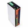
BUE-801 Series Substation Protocol Converters
BE-6000 Series Remote I/O Modules
IEC-60870-5-101 to IEC-60870-5-104(IEC-101 to IEC-104) Gateway
IEC-60870-5-101 to IEC-60870-5-104 Converter(Gateway)
BUE-801 series IEC-60870-5 Gateways can provides both industrial communication device and solution of the whole industrial automation system,which plays more important roles in industrial control and automation,especially in the substation automation.The IEC-60870-5 sub protocols can communicate with each other,eg. The BUE-801 supports IEC-101 to IEC-102,IEC-101 to IEC-103,IEC-101 to IEC-104,IEC-102 to IEC-103,IEC-102 to IEC-104,IEC-103 to IEC-104, IEC-101 to Modbus RTU/TCP,IEC-102 to Modbus RTU/TCP,IEC-103 to Modbus RTU/TCP, IEC-104 to Modbus RTU/TCP and IEC-101/102/103/104 to IEC-61850 and other substation communication protocols.
1.Communication function:
Protocol conversion:
Standard protocols that BUE-801 support: UCA2,OPC,TCP/IP, Serial, DNP3,OPC, Modbus RTU/TCP, IEC60870-5 series(IEC101,IEC102,IEC103,IEC104), IEC61850(Our IEC61850 Can work as server or client)
Non-standard protocol: DC screen,power meter,safety equipments.The different protocols of data can convert with each other in the BUE-801
Data processing:
Digital processing: signal acquisition & transmission,anti-shake,singnal maintenance, timing alarm, quality judgment.
Analog processing: multiplication coefficient, residual cleared, anti-mutation, quality judgment,etc.
Point table custom and information split:
In the BUE-801 system it provides different data forwarding point tables,different channels’ protocol can forward and each uses different data forwarding table. The same data can be submitted to the upper machine in the form of different value.
Dual channel processing:
BUE-801 Supports the system with dual channel mode and the upper machine communication, including fully redundant dual channel way, communication link redundancy, main equipment and so on.
Measuring point self description:
BUE-801 supports self description of data point, which is convenient for maintenance and debugging.
2.Advanced application:
Data calculation:
BUE-801 provides standard calculation formula and take the processing of data in the way of addition, subtraction, multiplication, division, logic judgment (including greater than, less than, equal to, is not equal to, greater than or equal to, less than or equal to, logic and logic, logic or, not), sine, cosine, square root, take maximum, minimum, average calculation.
Equipment automatic control can be set up:
BUE-801 provides the setting of basic control logic, timing or logical calculation according to the real-time data of on-site equipment start-stop switch quantity control and analog control, such as temperature, pressure, etc.
Advanced equipment control integration
3.Management function:
Debugging management:
BUE-801 provides all kinds of debugging methods and management, including remote debugging, intelligent device simulation, data simulation, control block, data browsing, message and debugging information monitoring, message storage and playback, flow rate and bit error rate statistics.
Equipment management:
Equipment management functions includes: remote diagnosis and maintenance, hardware watchdog, custom information indicator, main standby switch management etc.
Time synchronization:
BUE-801 can receive the time code from time servers,it can synchronizes time in the format of IRIG-B and NTP/SNTP.
4.System feature:
Low latency: 5 to 50ms latency.
Strong data processing ability.
Reliable communication management
5. Technical specifications:
Hardware:
10/100MTCP/IP: 2-6 nos
RS422/232/485 4-16 nos
DI/DO 8 nos
LED lights: 8nos
Wireless(GPRS/Zigbee/wifi/BD) 1 nos
Software:
Maximum channels:200
Maximum digital number/channel: 65536
Maximum analog number/channel: 65536
Maximum electric degree/channel: 65536
Maximum output/channel: 65536
Maximum analog output/channel: 65536
Data forwarding base: 4
Minimum data processing lantency: 5ms
Time synchronization precision:<1ms(Hardware synchronization)
Technical specs:
400Mhz Freescale MPC8308 CPU
128M DDR2 Memory
128M Nand Flash
2 Ethernet Ports
4 RS-232/485 Isolation Serial Ports
DIN-Rail Mount
|
System |
|
|
CPU |
Freescale MPC8308 PowerPC CPU,400MHz |
|
Memory |
DDR2 128M |
|
Flash |
8M Nor Flash |
|
128M Nand Flash |
|
|
Operating System |
Linux 2.6.29.6 |
|
LED |
|
|
|
System:Power x1,RUN x1, LAN:10/100/1000M x4(Link x2 Act x2) Serial:TxD x4,RxD x4 |
|
Others |
RTC,Buzzer,Watchdog Timer,Reset button,Console Port x1 |
|
Serial Communication |
|
|
Console Port |
Console Port RJ45 connector x1 RS232 115200bps N,8,1 |
|
Serial Port |
4 xRS-232/485 TB Interface connector software-selectable RS-232 Signals:TxD,RxD,GND RS-485 Signals:485A(Data+),485B(Data-) |
|
Protection |
Built-in 15KV ESD protection for all signals, 2KV iCoupler digital isolation protection |
|
Network Communication |
|
|
LAN |
Auto-sensing 10/100/1000Mbps x 2, RJ45 Build-in 1.5KV magnetic isolation protection |
|
Power Requirements |
|
|
Power Input |
Dual Power Input Design PWR1:9-48VDC or 9-48VAC PWR2:9-48VDC or 9-48VAC |
|
Lost power alarm |
Relay empty node |
|
Power Consumption |
|
|
|
8W@12VDC |
|
Mechanical |
|
|
Dimensions |
200(L)x121.01(W)x54.1(H) |
|
Installation |
DIN-Rail Mount |
|
Environmental |
|
|
Operating Temperature |
-20-60℃ |
|
Storage Temperature |
-30-80℃ |
|
Regulatory Approvals and Warranty |
|
|
EMC |
GB/T 17626.2-2006 Class 4 GB/T 17626.4-2008 Class 4 GB/T 17626.5-2008 Class 4 GB/T 17626.6-2008 Class 3 |
|
Warranty |
5 Years |
IEC-60870-5 (IEC101,IEC102,IEC103,IEC104) Protocol Gateways
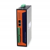
IEC101/102/103/104 Conversion Gateway
BUE-801 series IEC-60870 Gateways can provides both industrial communication device and solution of the whole industrial automation system,which plays more important roles in industrial control and automation,especially in the substation automation.The IEC-60870 sub protocols can communicate with each other,eg. The BUE-801 supports IEC101 to IEC102,IEC101 to IEC103,IEC101 to IEC104,IEC102 to IEC103,IEC102 to IEC104,IEC103 to IEC104, IEC101 to Modbus RTU/TCP,IEC102 to Modbus RTU/TCP,IEC103 to Modbus RTU/TCP, IEC104 to Modbus RTU/TCP and IEC101/102/103/104 to IEC61850 and other substation communication protocols.
1.Communication function:
Protocol conversion:
Standard protocols that BUE-801 support: UCA2,OPC,TCP/IP, Serial, DNP3,OPC, Modbus RTU/TCP, IEC60870-5 series(IEC101,IEC102,IEC103,IEC104), IEC61850(Our IEC61850 Can work as server or client)
Non-standard protocol: DC screen,power meter,safety equipments.The different protocols of data can convert with each other in the BUE-801
Data processing:
Digital processing: signal acquisition & transmission,anti-shake,singnal maintenance, timing alarm, quality judgment.
Analog processing: multiplication coefficient, residual cleared, anti-mutation, quality judgment,etc.
Point table custom and information split:
In the BUE-801 system it provides different data forwarding point tables,different channels’ protocol can forward and each uses different data forwarding table. The same data can be submitted to the upper machine in the form of different value.
Dual channel processing:
BUE-801 Supports the system with dual channel mode and the upper machine communication, including fully redundant dual channel way, communication link redundancy, main equipment and so on.
Measuring point self description:
BUE-801 supports self description of data point, which is convenient for maintenance and debugging.

2.Advanced application:
Data calculation:
BUE-801 provides standard calculation formula and take the processing of data in the way of addition, subtraction, multiplication, division, logic judgment (including greater than, less than, equal to, is not equal to, greater than or equal to, less than or equal to, logic and logic, logic or, not), sine, cosine, square root, take maximum, minimum, average calculation.
Equipment automatic control can be set up:
BUE-801 provides the setting of basic control logic, timing or logical calculation according to the real-time data of on-site equipment start-stop switch quantity control and analog control, such as temperature, pressure, etc.
Advanced equipment control integration
3.Management function:
Debugging management:
BUE-801 provides all kinds of debugging methods and management, including remote debugging, intelligent device simulation, data simulation, control block, data browsing, message and debugging information monitoring, message storage and playback, flow rate and bit error rate statistics.
Equipment management:
Equipment management functions includes: remote diagnosis and maintenance, hardware watchdog, custom information indicator, main standby switch management etc.
Time synchronization:
BUE-801 can receive the time code from time servers,it can synchronizes time in the format of IRIG-B and NTP/SNTP.
4.System feature:
Low latency: 5 to 50ms latency.
Strong data processing ability.
Reliable communication management
5. Technical specifications:
Hardware:
10/100MTCP/IP: 2-6 nos
RS422/232/485 4-16 nos
DI/DO 8 nos
LED lights: 8nos
Wireless(GPRS/Zigbee/wifi/BD) 1 nos
Software:
Maximum channels:200
Maximum digital number/channel: 65536
Maximum analog number/channel: 65536
Maximum electric degree/channel: 65536
Maximum output/channel: 65536
Maximum analog output/channel: 65536
Data forwarding base: 4
Minimum data processing lantency: 5ms
Time synchronization precision:<1ms(Hardware synchronization)
Technical specs:
400Mhz Freescale MPC8308 CPU
128M DDR2 Memory
128M Nand Flash
2 Ethernet Ports
4 RS-232/485 Isolation Serial Ports
DIN-Rail Mount
|
System |
|
|
CPU |
Freescale MPC8308 PowerPC CPU,400MHz |
|
Memory |
DDR2 128M |
|
Flash |
8M Nor Flash |
|
128M Nand Flash |
|
|
Operating System |
Linux 2.6.29.6 |
|
LED |
|
|
|
System:Power x1,RUN x1, LAN:10/100/1000M x4(Link x2 Act x2) Serial:TxD x4,RxD x4 |
|
Others |
RTC,Buzzer,Watchdog Timer,Reset button,Console Port x1 |
|
Serial Communication |
|
|
Console Port |
Console Port RJ45 connector x1 RS232 115200bps N,8,1 |
|
Serial Port |
4 xRS-232/485 TB Interface connector software-selectable RS-232 Signals:TxD,RxD,GND RS-485 Signals:485A(Data+),485B(Data-) |
|
Protection |
Built-in 15KV ESD protection for all signals, 2KV iCoupler digital isolation protection |
|
Network Communication |
|
|
LAN |
Auto-sensing 10/100/1000Mbps x 2, RJ45 Build-in 1.5KV magnetic isolation protection |
|
Power Requirements |
|
|
Power Input |
Dual Power Input Design PWR1:9-48VDC or 9-48VAC PWR2:9-48VDC or 9-48VAC |
|
Lost power alarm |
Relay empty node |
|
Power Consumption |
|
|
|
8W@12VDC |
|
Mechanical |
|
|
Dimensions |
200(L)x121.01(W)x54.1(H) |
|
Installation |
DIN-Rail Mount |
|
Environmental |
|
|
Operating Temperature |
-20-60℃ |
|
Storage Temperature |
-30-80℃ |
|
Regulatory Approvals and Warranty |
|
|
EMC |
GB/T 17626.2-2006 Class 4 GB/T 17626.4-2008 Class 4 GB/T 17626.5-2008 Class 4 GB/T 17626.6-2008 Class 3 |
|
Warranty |
5 Years |
IEC 61850 Application in Railway Traction Substation Monitoring and Control System
IEC 61850 Application in Railway Traction Substation Monitoring and Control System
Preface
By the end of 2005, the total mileage of electrified railway in our country has more than 20000 km, traction substation of primary and secondary equipment variety, different interface standard, technical equipment level differences between different regions, so the traditional traction substation telecontrol system cannot meet the needs of multiple substation remote monitoring. How to utilize the high coverage of the Internet, through the seamless connection of information technology, build an efficient, inexpensive traction substation remote monitoring system has become a hot topic of concern.
IEC 61850 is IEC TC 57 in UCA 2.0 American experience and the IEC 60870 series standards of the European experience about the future of substation automation system is proposed on the basis of the communication system standard. The goal is to maximize the application of existing standards and widely accepted, the communication principle of intelligent electronic devices (ieds) in different manufacturers to achieve good interoperability between, and can adapt to the rapid development of communication and application technology. IEC 61850 is different from the traditional SCADA protocols, it is not a simple protocol, performance requirements, more involved in communication network object modeling, system and project management aspects of the specification requirements.
IEC 61850 adopts object oriented modeling method and abstraction, hierarchical mapping technology, through the specification system and project management, as well as conformance testing way to ensure the realization of the goal. And IEC 61850 is not only applicable to internal substation automation network communication, can also be applied to distribution automation, electric energy metering system, power plant automation system, wind power and other industrial automation field.
Based on the analysis of the status quo of traction substation equipment in China, on the basis of established based on IEC 61850 standard of traction substation communication system model of sub station and control center, dynamic information meet with IEC 61850 standard XML specification describes the monitoring center using IE browser, Java Script, and the Active X controls, implement multiple traction substation remote monitoring, on the premise of not to refresh the IE browser page to realize the dynamic display of the operation parameters and status.
1 The content and features of IEC 61850 standard
1.1 The contents of the IEC 61850 standard
In the early 1990 s, Europe and the United States has carried out the research at the same time, and formulate the corresponding standards. In order to avoid conflict, two standard IEC decision on the basis of UCA 2.0 data model and service, incorporate the results of UCA IEC standards, establish a worldwide uniform standard, IEC 61850, and formally approved in 2002. In terms of concepts, the IEC 61850 standard draft mainly around the following four aspects:
(1) function modeling. From the substation automation communication system communication performance (PICOM) requirements, defines the function model of substation automation system.
(2) data modeling. Using object-oriented method, defines the data model based on client/server structure.
(3) the communication protocol. Defines the data access mechanism (service) and to the mapping of the communication protocol stack, such as the transformer substation layer and intervals between the network USES the abstract communication service interface is mapped to the MMS (IEC 61850-8-1). In the interval between the layer and process layer network mapping into serial unidirectional multipoint or point-to-point transmission network (IEC61850-9-1) or the process of mapping based on the IEEE 802.3 standard bus (IEC 61850-9-2).
(4) the substation automation system engineering and conformance testing.
Definition based on XML (Extensible Make up Language) structured Language, describe the topology and substation automation system and IED structured data. In order to validate interoperability, Part 10 describes the IEC 61850 standard conformance testing.
1.2 the characteristics of IEC 61850 standard
The main characteristic of IEC 61850 standard has the following several aspects: (1) the hierarchical information. IEC 61850 substation communication network and system agreement draft standard puts forward the concept of stratification within the substation information, no matter from the concept of logic or from the physical concept, substation communication system are divided into three levels, namely the substation layer, spacing layer and process layer, and defines the communication interface between layer and layer.
(2) object-oriented unified modeling data object. IEC61850 standard USES the object-oriented modeling technology, defines the data model based on client/server structure. Each IED contains one or more servers, each server itself contains one or more logical device. Logic device contains logical node, logical node contains data objects. A data object is composed of data attribute public data named instance of a class. In communications, IED also play the role of the customer. Any customer can use the abstract communication service interface (ACSI) through the server to access the data object.
(3) the data from the description. With IEC 60870-5 series standard adopts some oriented data description methods, IEC 61850 standard for information adopts object-oriented self-describing. The self-describing self description of the data itself in data source, data is transmitted to the receiver with the self, don't need to for engineering data quantity, scale conversion, etc. Because the data itself with instructions, so transmission can be defined in advance without limit, simplifies the data management and maintenance work. For this purpose, the IEC 61850 standard provides a set of object-oriented data from description method: IEC61850 object name standard defines the equipment name, logical node name, instance number and the name of the class data to establish object name naming rules; IEC 61850 communication service standards using object-oriented method, defines the communication between the service object, for example, to get and set object values communication service, obtains the object list of communication services, data object value obtained a list of services.
(4) the abstract communication service interface (ACSI). IEC 61850 standard summarizes the necessary Communication services, information transmission in substation was designed independently of the network and the application layer protocol used by the Abstract Communication service interface (the Abstract Communication ServiceInterface, ACSI). In IEC 61850-7-2, the established standards compliant server must be provided by the communication service model, including the server model, logical device model, data model, data model and logic node set model. Customers by ACSI, by special Communication Service mapping (Specific Communication Service Map, SCSM) mapped to Specific protocol stack, such as Manufacturing Message Specification (Manufacturing Message Specification, MMS).
2 Traction substation sub model of communication
Our country existing traction substation automation equipment used by a wide variety, interface standards also each are not identical, some use RS232 / RS485 interface, some with TCP/IP interface, there are a few equipment has been using IEC 61850 standard interface. In order to adapt to a variety of configuration system, Beijing jiaotong university institute of electric power system and system control technology co., LTD Beijing DeWitt force joint design for traction substation child general communication model, and applied to the actual remote monitoring system of traction substation, sub station communication model is shown in figure 1.
Sub station communication machine has two functions: through RS232 / RS485 or TCP/IP interface to the underlying substation equipment real-time parameters and status information collected and stored in the local database; Establish a two-way Socket communication with the monitoring center via the Internet, according to the request from the monitoring center, the real-time data and state of the local database, and compatible with IEC 61850 standard equipment real-time information together, according to the IEC 61850 standard repackaged into XML file upload, also will command from the monitoring center according to their respective specifications (RS232/485 or IEC 61850) is forwarded to the underlying device is carried out. Communication machine generated upload Devices. The XML file.
A typical traction substation to upload the XML file size is about 2.82 kB. Sub station communication machine Socket communication between master station and once established, sub station is in a state of circulation to send.
3 Remote monitoring system of traction substation
Monitoring master station, located in the center of the electric power dispatch of each traction substation is through the Internet and communication machine set up the Socket communication, the system structure is shown in figure 2.
The front end of the monitoring system of monitoring and control system using IE browser, through the Java Script in the HTTP call Microsoft XMLDOMActiveX control, establishing the Socket communication with sub station communication machine, upload the XML file, according to monitor the user's requirements in real time. Specific implementation is as follows:
Among them, the "221.137.24.108:8080" said a certain traction substation communication machine IP address and Port number. So, in a similar way in monitoring master station from all monitored a communication machine reading real-time data and status, statistical analysis, according to the requirement of the user in the form of statement or graphics (such as using Java Applet technology) for display. Other users have access to monitoring master station all can see through their Internet explorer and standing on the same picture. With a Socket send way of communication and circulation, the client IE without page refresh, you can display system of real-time data and status.
4 Conclusion
This paper puts forward a kind of based on IEC 61850 electrified railway traction substation remote monitoring system, traction substation station and the communication between the monitoring center is used to meet the IEC 61850 standard XML and Socket communication way. Sub station is responsible for the collection of traction substation in real-time data stored in the local database, and upon the request of the monitoring master station, the dynamically generated XML file sent cycle. Main use IE browser, Java Script and Active X technology and multiple child stand to establish a Socket communication, on the premise of not to refresh the IE browser page to achieve real-time data and status of the system dynamic refresh. In this paper, the remote monitoring system through the Internet station connected to the monitoring center, without special telecontrol channel, greatly reduces the system cost, the XML technology based on IEC 61850 standard is linked together, to realize the seamless connection between each subsystem.
The 2nd Youth Olympics held in Nanjing
The second Youth Olympics are officially under way, following a brisk Opening Ceremony in Nanjing, China, on Saturday night.
“Dear youth athletes, these are your Games,” International Olympic Committee president Thomas Bach said inside Sports Centre Stadium. “This is your moment.”
Bach then called for an unprecedented action at an Opening Ceremony, asking the young athletes in attendance (more than 3,000 will take part overall) to take out their cell phones and “set a record for selfies.”
Four-time Olympic champion diver Chen Ruolin capped the night by lighting the Youth Olympic cauldron.
NBCSN and NBC Sports Live Extra will have coverage of the Opening Ceremony on Saturday from 6-8 p.m. ET. (full NBC Olympics, Universal Sports coverage of the Youth Olympics here)
The ceremony included much of the standards from Olympic Opening Ceremonies. The Parade of Nations, which can take up to two hours at an Olympics, was a Parade of Flagbearers in Nanjing, taking 35 minutes.
Chinese Olympic legends, including diver Wu Minxia and hurdler Liu Xiang, brought out the Olympic Flag to be raised.
The artistic portion of the evening was a little reminiscent of the unforgettable and unparalleled Beijing 2008 Olympic Opening Ceremony. Of course, it involved far fewer participants and was on a smaller scale, but the performers, fireworks and installations (including a large telescope) were top quality.
The Youth Olympics will include 222 events across 32 sports through Aug. 28. Nanjing is the second summer edition of the Youth Olympics, following the Singapore debut in 2014. Youth Olympic athletes range in age from 14 to 18.
The U.S. athlete delegation of 92 includes Opening Ceremony flag bearer Kendall Yount, a taekwondo athlete.
BuenoElectric Remote I/O Modules Finally Came out
With years efforts made by Bueno technical Team,the Distributed Remote I/O Modules series products were finally worked out and successfully passed the testing made by related authority.We are positive that these series products would bring the impact onto the I/O market.
Bueno I/O modules series are based on 3 protocols: Modbus RTU(ASCII),Modbus TCP and CAN. And the hardware interfaces are RS-485 terminal and Ethernet. The function categories include DI,DO,AI,AO,power relay,TC and RTD.We can cover most functions that the inudstrial projects requires.
With mature technology and high quality components and chips, our I/O modules series will be a black horse in this industry.In the future, we are scheduled to develop out more prorotocls like CANOpen,DeviceNet,BacNet and etc,which would be the great supplement to our product and protocol ranges.
2 Channel CAN PCI Card
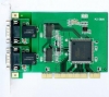
2 Channels Isolated CAN Bus PCI Card
- Introduction:
The PCI-CAN card is a Controller Area Network (CAN) interface card. It supports one or dual-port CAN's interface that can run independently or bridged at the same time. The built-in CAN controller of this card is Philips SJA1000, which provides bus arbitration and error detection with auto correction and re-transmission function.
- Features of Our CAN PCI Card:
Passive CAN Interface for PCI slots
One, two CAN channels with Controller NXP SJA1000
Baud rates up to 1MBaud, 82C251 Transceiver
CAN is connected via a 9-pin SUB-D as defined by the CiA DS102-1 standard
CAN 2.0A (11-bit ID standard frames) and 2.0B (29-bit ID extended frames)
Development kits for Windows 2000/XP/Vista
Examples of Visual Basic 6.0, Visual C++ 6.0, C++builder 6.0, Delphi7.0, Labview are available
Max data flow 3000 fps (extend frame)
Operating temperature: -25 to +85C
-
Application of Our CAN PCI Card:
CAN-bus product development, CAN-bus data analyzer, CAN-bus master/slave network, CAN-bus Teaching applications,CAN-bus gateway/bridge,CAN-bus industrial control & automation,Smart building system, Data transfer between different CAN-bus networks.
Example Topology Figure:

Ordering Information:
|
Model number |
CAN Channel |
Work temperature |
Description |
|
BUE-CAN-PCI-5810I One Channel CAN-PCI Card |
1 |
-25℃~+85℃ |
Industrial PCI to 1 CAN |
|
BUE-CAN-PCI-5820I 2 Channels CAN-PCI Card |
2 |
-25℃~+85℃ |
Industrial PCI to 2 CAN |
|
BUE-CAN-PCI-6810I One Channel CAN-PCI Card |
1 |
0℃~+70℃ |
Intelligent PCI to 1 CAN |
|
BUE-CAN-PCI-6820I 2 Channels CAN-PCI Card |
2 |
0℃~+70℃ |
Intelligent PCI to 2 CAN |