Sidebar
News Press

Administrator
BE Offered Modbus RTU to TCP Conversion Solution for Clients
BE Offered Modbus RTU to TCP Conversion solution for a water project in Thailand and solved the communication problem between pair twisted and ethernet networks.Please download the PDF from this webpage.
BE's Profibus DP to PA Converter Application Case
BE's Profibus DP to PA Converter successfully installed in Indian industrial control project connecting to AB's control unit,for further study please download the PDF from this page.
China's Fiber Optic Industry Rising
In the past 5 years of development, expansion of optical fiber industry in China to nearly 400%, accounting for 42% of global market, the Chinese market in the global optical fiber occupy a pivotal position in the market. At the same time, also a comprehensive breakthrough core technology, expanding to the industrial chain of upstream. Balefire communication introduce to the peak, vice President of the bear, due to the large-scale construction FTTx and 3 g network, stimulated the rapid rise of the domestic optical fiber industry, light sticks, optical fiber, optical cable industry system has been gradually perfected.
Domestic enterprises accounted for half the world's top 10 spots
From CRU, according to data from the world's top ten enterprises in successive years of change, China faces more and more, in the current market share of the top 10 firms have five Chinese companies, including yofc accounted for 6.4%, 6.1%, balefire communication fortis 4.5%, 4.1%, prosper photoelectric zhongtian technology 3.8%. From the perspective of a domestic industry development, the industry collectivization, the whole industry chain layout and further speed up the pace.
Bears to the peak, points out that from the point of the global market, the entire optical fiber demand growth, at the same time the capacity of the fiber is a trend of rapid growth, in 2012 is expected to start a new round of release, the biggest influence in China.
From the point of the price movements of optical fiber, as a result of the Japanese earthquake effect of earlier this year, and raw material prices make optical fiber preform, delayed the fiber price decline, with China's further release, however, it will be hard to stop cost fiber prices continued to decline in line.
Internationalization is imminent
Look at domestic cable enterprise development, is still rooted in the domestic market, mainly in industrial clusters in jiangsu, hubei industrial clusters and industrial clusters in sichuan, zhejiang industrial clusters, guangdong industrial clusters is given priority to, in the development of fiber industry background, the domestic enterprises to enter the overseas market is the necessary way of development. Bear to peak further pointed out that compared with the overseas counterparts, the domestic enterprise market ability is weak, including brand, market expansion and development cost, satisfy the customer, the layout of the lack of long-term, it is difficult to compete with overseas enterprise, from the aspects of implementation capability, however, domestic enterprises have the overseas development strength, from design, manufacturing, delivery and quality to cost, efficiency, already have a certain ability to export, especially in the manufacturing and cost, domestic companies have greater advantages.
Troubleshooting to the CAN Transceivers in the Electrical Bus
The CAN transceiver is a CAN bus communication signal transmission channel, transforms the TTL level of single chip microcomputer for CAN bus level, is CAN standards - the most basic physical layer chip ISO11898 series. If the CAN transceiver is abnormal or failure, this node will be affected by the deadly of communication.

In the operation of electric buses, the engineer is the most afraid of the scene in "downs", if not thoroughly CAN node communication, is a good chance that transceiver is damaged, replace it; If fault occurs when the vehicle running, but when the fault node down test, the but again can work normally, this is very headache.
Electric bus and conventional bus is different, it is the use of batteries, capacitors to store energy, and then through the inverter into communication, drive motor drive the vehicle. When coach acceleration or deceleration, inverter produces huge current changes, to form a strong magnetic field interference, through the power cable coupling to the nearby CAN bus, CAN make the CAN transceiver damage rate increased. And in some cases, the CAN transceiver is working in the damaged condition, is what we call "downs" phenomenon. According to the general test standard is hard to find and calibration failure, can't timely troubleshooting node in vehicle maintenance. Recently some electric bus is encountered a case of damage
CANScope eye diagram analysis method
Eye diagram is logic pulse overlap, used to measure the signal quality. Popular point, that is, all the "0" and "1" superposition together, observation, signal distortion degree of a statistical method.
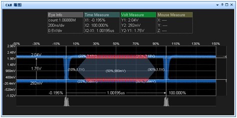
Regulations such as the CAN - bus ISO11898-1 dominant logic of differential input voltage is greater than 0.9 V. As shown, if you want to make a CAN bus communication, normal eye diagram grey area the level of the minimum not less than 0.9 V. Figure used in CANScope hardware the eyes of the eye diagram function to measure high of 1.75 V, is to meet the requirements of communication.
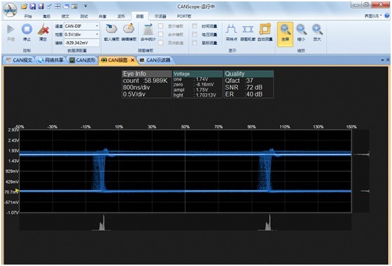
eAN anser with normal waveform eye diagram
For electric passenger cars on normal doing eye CAN node figure, there is no obvious distortion.
Visible to fault doing eye diagram, CAN node fault node though the CAN communication, but the waveform distortion has already happened. More than dominant threshold has amounted to 4.3 us the width of 0.9 V, it indicates that the fault node at this time the dominant level (logic 0) the width of 4.3 us, and standard deviation 0.3 4 us have us.
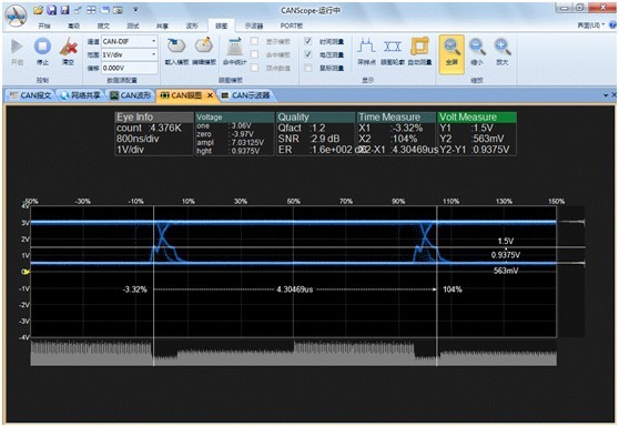
We can see that in the case of temperature change, the bit width will increase, resulting in abnormal bus baud rate, all nodes will be its interference, because the program made since the restore function, so the fault node unable to exit the bus, bus has been interference, eventually lead to paralysis of the vehicle.
Our CAN Multi-drop Bus FO Converter In German Projects
Our CAN Multi-drop Bus FO converter In German Projects,the converters super function was highly praisded by the integrator. The series is our competive product which has the most advanced performance in the world.For case study,please download the PDF file from this page directly.
Maximum Cable Length For a CAN Bus
Problem:
I am building a CAN bus and I need to know the maximum length of the CAN Bus, or the maximum distance between end Nodes. Additionally, what is the maximum distance that any Node can be from the main CAN bus? Lastly, what values should I use for my termination resistors?
Solution:
The CAN bus is designed to be setup using a bus network topology. You cannot use a star or a ring topology. The CAN specifications limit how far a device can be attached from the bus. Below is an illustration that depicts how the bus should be setup. 
If you are using a fault tolerant or low-speed bus it will require you to provide termination at every node. If you have a high-speed bus it will require termination at the two ends of the bus. Generally you would place the Master at one end of the bus (node 1) but It is also possible to have the master connected in the middle with no termination, with termination at the nodes at the end of the bus line.
| Bus Speed | Bus Length (L) |
Cable Stub Length (l) |
Node Distance (d) |
| 1 Mbit/Sec | 40 meters (131 feet) |
0.3 meters (1 foot) |
40 meters (131.2 feet) |
| 500 kbits/Sec | 100 meters (328 feet) |
0.3 meters (1 foot) |
100 meters (328 feet) |
| 100 kbits/Sec | 500 meters (1640 feet) |
0.3 meters (1 foot) |
500 meters (1640 feet) |
| 50 kbits/Sec | 1000 meters (3280 feet) |
0.3 meters (1 foot) |
1000 meters (3280 feet) |
If a cable stub (un-terminated cable) or T-connector is used to tap into the bus line, then the stub distance should not exceed 0.3m at 1Mbit/s rate per. DS 102 Version 2.0.
Termination Resistors
Termination Resistors are used to impede reflections on the line. To determine the value of the termination resistors look at the Impedance of the cable and match the resistors to it. For a normal CAN bus cable with a 120 ohm line impedance you should use 120 ohm resistors.
Lonworks and BacNet
Introduction
Over the course of the past fifteen years, building owners, managers and consulting/specifying engineers have become increasingly frustrated by incompatibilities and limited opportunities for the integration of building automation and control systems. Although the sophistication and flexibility of networking and communications technologies in general have been increasing geometrically, controls systems for buildings have carried forward a legacy of proprietary thinking which has impeded the natural migration of many of the benefits of open networking technology into building systems. The bottom line effect has been that, while many modern building automation and control systems incorporate some of the latest advances in networking technology, the benefits of interoperability, configuration flexibility, and performance-based pricing have yet to be realized by building owners and operators. Through accident or intent, building automation and controls systems have simply failed to embrace true open systems concepts effectively for building owners.
Several solutions have become available recently which promise to change this situation permanently and dramatically. One such solution is called BACnet™: The Building Automation and Controls Network. BACnet is a standard for computers used in building automation and controls systems that has been developed over the past nine years by ASHRAE. In December of 1995, BACnet was also adopted by ANSI, and is now an American National Standard (ANSI/ASHRAE 135-1995). Nearly every major vendor of building automation and controls systems in North America has demonstrated support for BACnet in the form of new products, many of which have been displayed at the annual AHR/ASHRAE show in Atlanta this year. Another completely different solution is called LonWorks® which is a proprietary communications technology which has been marketed for several years by the Echelon Corporation in partnership with Motorola. Various vendors have used LonWorks successfully in recent years to provide solutions for small controls systems applications, in some cases involving multiple vendors.
This paper will explore both of these systems in some detail to help bring into focus the substantial differences between each approach. We will also focus on various popular myths in order to dispel some of the confusion and misinformation that has surfaced as these different solutions have been introduced to the marketplace.
WHAT IS BACNET?
BACnet is an American National Standard. This is literally a book which describes in great detail how to create an automation and controls system which may interoperate with other BACnet systems. In BACnet terms, interoperate means that two or more BACnet-speaking computer systems may share the same communications networks, and ask each other to perform various functions on a peer-to-peer basis. Although BACnet does not require every system to have equal capabilities, it is possible for designers of system components at every level of complexity to have access to functions of other automation system peers. In the BACnet world, there is no class distinction between large controllers, small controllers, sensors, actuators and operator workstations or host computers.
There are two key concepts in BACnet that are critical to understand. First, is the idea that BACnet is applicable to all types of building systems: HVAC, Security, Access Control, Fire, Vertical Transport, Maintenance, Waste Management, Lighting, and so forth. The same mechanism that gives BACnet this flexibility has two other important benefits: vendor-independence and forward-compatibility with future generations of systems. This is accomplished using an object-oriented approach for representing all information within each controller. The second key idea is that BACnet uses any combination of five types of local area network or LAN technology for transporting BACnet application messages. These five types of LAN choices give the system designer or owner significant flexibility in choosing the best fit among price/performance options that suits each situation. Four of the five LAN options are ANSI or international (ISO) standards. Since BACnet is based on standards, it provides maximum benefits for both the vendor who designs BACnet systems, and the specifier or owner of those systems.
BACnet provides a sophisticated model for describing automation systems of all types. This model is based on the idea that for systems to be truly interoperable, there must be some agreement about various aspects of the overall operation and the individual systems themselves. BACnet organizes its model into these component parts:
Objects to represent system information and databases, along with a uniform method for accessing both standardized and proprietary information
Services which allow BACnet devices to ask each other to perform various functions in standardized ways
LANs which provide transport mechanisms for exchanging messages across various types of networks and communications media
Internetworking rules which permit the construction of large networks composed of different LAN types
Conformance rules which define standardized ways of describing systems in BACnet terms, and standardized forms for describing which optional features of BACnet a given system provides
Each of these components delivers important benefits to purchasers and specifiers of BACnet systems.
Objects
BACnet's object-oriented approach to accessing and organizing information provides a consistent method for controlling, examining, modifying and interoperating with different types of information in different types of devices, which is both vendor-independent and forward-compatible with future BACnet systems. BACnet defines standard object types that represent commonly used objects found in many existing automation systems. BACnet objects are collections of properties each representing some piece of information or parameter. Some properties may only be examined (read) while others may also be modified (written). BACnet defines not only what the properties of standard objects are, but also what types of behavior are to be expected from each property. Standard objects also have optional properties, which need not be implemented by every vendor, but if they are implemented then they must behave as the standard describes. These standard objects may also have proprietary properties that are added by vendors at their discretion to provide additional features. A BACnet device may also implement proprietary object types that can provide any type of feature or set of properties that the vendor chooses. The key to the object mechanism is that every object and every property, whether standardized or proprietary, is accessible in the same manner. To use a proprietary object or property, you need only know of its existence and purpose. Of course, one vendor's system may not necessarily "know" about all possible proprietary objects and properties in another vendor's systems.
BACnet is not a guarantee that forces all systems to be the same, or even an assurance of interoperability. BACnet does provide the mechanism to allow cooperating devices to interoperate if they choose to.
Services
BACnet services provide standard methods for one BACnet device to ask another BACnet device to do something, or to inform other BACnet devices that something has happened. For example, if one BACnet device needs to find out something, like a temperature, it can use the ReadProperty service to read a property of an object in the other device that represents the temperature. Similarly, the WriteProperty service can be used to make adjustments in another device, like changing a setpoint property. BACnet defines a comprehensive range of different services that cover access to objects and their properties, alarms and events, device and communications management, file transfer and virtual terminals. As with standard objects, not all devices are required to or will choose to implement all services. Vendors may also provide Private Transfer services to make new proprietary services available.
LANs
BACnet allows systems to use any of five types of Local Area Network, or LAN, technology. These different choices represent a range of different features, cost and performance, so no one technology is desirable or appropriate for all applications in automation systems. Each LAN type has unique benefits and liabilities that may make it preferable in one situation or another. We will talk about these issues in a later section. The LANs available to BACnet systems are:
Ethernet
ARCNET
MS/TP
PTP
LonTalk
Internetworking
Real networks in real buildings need to interoperate together. The network that operates all of the VAV Terminal boxes on one floor of a building needs to be accessible, not only to the air supply system for that floor, but to the building management as well. In a multi-building campus, or dial-up applications, the system must necessarily be composed of multiple separate networks that have intermittent reasons to interact between devices on two or more networks. Not all of these networks will use the same LAN technology, for reasons of cost and performance. Because there are multiple networks, we have several issues to confront:
getting information from devices across multiple networks
controlling and isolating unrelated message traffic between networks
interfacing disparate LAN technologies and signaling
Internetworking addresses each of these issues. One of BACnet's key strengths is the sophistication and flexibility of its internetworking that is achieved at only a modest cost to most BACnet devices. Typically internetworking is accomplished in BACnet using special devices called routers which couple two or more different networks together. Although BACnet routers can use the same LAN technology on each end of a router, more typically routers are used to couple different LAN types together. The important thing to keep in mind is that a BACnet router couples together two or more BACnet LANs.
It is also possible to have devices called gateways which couple a BACnet LAN to a non-BACnet LAN, perhaps using a proprietary communication scheme. Gateways are inherently more complex than routers because in addition to equalizing the differences between LAN types, gateways must also manage the usually vastly different conceptual model of one application protocol with another. This task may range from straightforward to very difficult or impossible in some cases.
Conformance
As a standard, BACnet describes mechanisms that, if properly applied, can result in systems from different vendors that may interoperate with each other. The big "if" is that each system must implement the features of BACnet that the other system(s) require. Having implemented a BACnet system, a vendor needs a method of telling others what has been implemented. To purchase or specify a BACnet system, one needs a method of describing which BACnet features are desired. To meet these needs, BACnet specifies two methods for describing BACnet features and a method for describing a BACnet implementation.
BACnet defines six broad categories of conformance classes that describe general features of BACnet which a device of that class must provide. Generally speaking, a higher numbered class means that more features are implemented. However, class is not sufficient by itself to specify a BACnet device. For example, a class 2 BACnet device must provide both the ReadProperty and WriteProperty services, but only one standard object (the Device object) is required. In practice, you would want to specify also those BACnet standard object types that you were looking for, so class by itself doesn't do the job. BACnet also describes what are called functional groups which are collections of BACnet features (services, objects and required properties) that are required to realize certain common functions, such as Alarm Reporting or File Transfer or Virtual Terminals.
To facilitate the description of a BACnet implementation, either one a vendor has made, or one that a purchaser would like to buy, BACnet defines the Protocol Implementation Conformance Statement or PICS. The PICS defines the information that must be provided to identify all of the key features of a BACnet device. The PICS identifies the manufacturer, make and model, the conformance class, which functional groups are supported, which standard objects are present, which optional properties of those objects are implemented, the acceptable range of values for writable properties, what type of LANs are supported with what types of media, etc.
Although not required by BACnet, the astute specifier or purchaser should also require that all of the objects and properties of every BACnet device should be documented, especially proprietary ones. This documentation should include not only the object type and property identifiers, but the range of acceptable or producible values and a description of the operation and meaning of each property and what it represents or controls.
Summary: What is BACnet?
BACnet is an American National Standard which defines methods for organizing applications and databases used within automation systems so that they may interoperate with each other across multiple types of LAN and media combinations. The standard further specifies standard mechanisms for describing typical types of objects and processes which may exist in automation systems, methods for extending this functionality into future and present proprietary systems, and methods for specifying and describing BACnet functions and features in standardized ways.
BACnet systems are realized by sending and receiving messages across various types of transport mechanisms (LANs) using a common communications protocol.
Nearly every major vendor of building automation and controls systems in North America has participated in the development of BACnet, and have either demonstrated or are actively selling BACnet-based controls today. Given that the standard has only been "official" for six months, this is a strong indication of what to expect going forward.
WHAT IS LONWORKS?
LonWorks is actually a family of products originally developed by the Echelon Corporation. At the core of this technology is a proprietary communications protocol called LonTalk. In this context, the term "proprietary" means that the technology was initially owned by a single proprietor, namely Echelon. A communications protocol is a set of rules that describe methods which can be used to manage the exchange of messages between cooperating devices that implement the protocol. The LonTalk protocol uses some advanced ideas that are unique to Echelon and their products. Because of the complexity of some of these ideas, Echelon's designers decided to develop a special type of communications "chip" which was uniquely well suited to implementing LonTalk. Using this chip, and the appropriate software, much of the burden of implementing LonTalk can be absorbed completely by the communications chip, freeing the rest of the system for application tasks. This communications chip is called the Neuron®. Echelon eventually licensed the chip design to Motorola under a royalty agreement. Motorola has since become a substantial investor in Echelon. As is their standard practice for most chip designs, Motorola has a cross-licensing agreement with another chip manufacturer, Toshiba. Together, Motorola and Toshiba market the Neuron world-wide to various types of OEM developers who apply the LonTalk technology in different markets and applications.
LonTalk is like a very simple mailing system that provides system designers with some basic mechanisms for transporting messages between systems. In and of itself, LonTalk does not define what these messages contain. Like the U.S. Postal system, LonTalk merely provides a way to send a "message" to another recipient. Various options for sending may be used, but the "postal system" doesn't really care what the message says, or whether the recipient can even understand it.
For the message system of LonTalk to be useful in a given application, the sender and receiver need to agree on the content of these messages. Since Echelon's designers had a fairly good idea of some of the applications that the Neuron and LonTalk might be used for, they were able to develop a second protocol that could be used to define the content of application messages. This "one size fits all" protocol represents the session, presentation and application layers of LonTalk and is often referred to as LonWorks.
In this paper we will make the distinction between the lower layers of LonTalk and the upper layers by consistantly calling the upper layers "LonWorks."
Controllers that make use of LonWorks can communicate with each other through what LonWorks calls "Standard Network Variable Types" or SNVTs (pronounced "snivets"). The SNVT method is a different approach to defining data objects that requires a detailed knowledge on the part of the sender and receiver of what the structure of each SNVT is. SNVTs are identified by a code number that the receiving controller can use to determine how to interpret the information presented in each SNVT.
The open-ended nature of SNVTs is both a strength and a liability. The liability comes from the fact that since LonWorks does not define what a particular SNVT code represents, it is possible, and regrettably commonplace, for LonWorks systems from different vendors to use the same SNVT code to mean different things. At best this causes confusion when these systems are coupled together, and at worst causes inappropriate actions to be mistakenly taken. To help solve this problem, a consortium of Echelon vendors was formed to try to agree upon some rules for how LonWorks should be used, and to agree on a common set of SNVT codes and their associated meanings. This group is called The LonMark® Consortium, and the documents that they have produced are also commonly referred to as LonMark. In theory, controllers that only use the LonMark subset of LonWorks capabilities can be made to interoperate with each other, and at least not interfere with each other's proper operation. The LonMark Consortium members must pay substantial membership fees for their on-going participation in LonMark. Only the highest paying tiers of members may vote on extending LonMark capabilities.
LonWorks Problems
Although LonWorks has been applied in various markets for some years now, only recently have some vendors in the building automation and controls market begun to offer products based on the Echelon technology. In the context of building automation and controls applications, some vendors have used the innate ability of Neurons to contain applications in addition to communications, as a means of offering both the application and networking capabilities at a modest cost. The flexibility of using different media types with Neurons is realized with transceiver devices which plug on to a common foundation, making it possible, by design, to use different media types with the same device. So more capable transceivers can be plugged in to increase performance without changing anything else. Of course, more performance comes at a higher cost.
Initially, various vendors appeared in the marketplace with products implemented based on LonWorks. Many had bought into the promise of automatic interoperability as a "free" consequence of using the Neuron and LonWorks. As previously mentioned, this turned out to be problematic. The formation of LonMark, though envisioned as a solution to this problem, has brought forward various new problems. While LonMark has created an industry consortium to attempt to standardize on implementations of LonWorks, there is still a lot of confusion and very little actual interoperability.
Let's focus on several myths and misconceptions about LonMark, LonWorks, LonTalk and their relationship to BACnet.
One major problem is that LonMark is not extensible without the agreement of "gold level" LonMark members. So vendors who need to add functionality to their systems may not do so without violating their agreement to adhere to LonMark (therefore losing the right to bear the LonMark mark), or convincing the golden members to bless their extensions. For purchasers or specifiers, this restricts your choices to "gold member approved" features and functions (of course provided only by their companies). Since LonMark is not a standards body, features may come and go as members elect, so no assurances of forward compatibility can be made in good faith by any LonMark member, since future changes or enhancement may easily compromise backward compatibility.
A second problem is that not all systems are LonMark systems. It is both possible and probable that LonWorks will continue to be used by some vendors who do not wish to, or cannot afford to, buy in to the LonMark consortium. Since the primary justification to applying LonWorks is the alleged attraction to integrating communications with an application in the same device (i.e. Neuron) to lower costs, then development cost, manufactured cost and ongoing support cost are clearly important issues.
BACnet LANs Revisited
This table briefly summarizes each technology. The system cost per node represents the cost of using this technology in a real system including issues like wiring costs, installation costs, the need for repeating devices etc.:
LAN system cost per node speed pros cons
Ethernet high 10-100Mbps
international standard
already in most buildings
variety of media (UTP, coax, fiberoptic)
very fast
easy interface with PCs
no special development tools
high cost
distance limitations
non-deterministic
ARCNET med 150K-7.5Mbps
ANSI standard
deterministic response
scaleable speed
variety of media (UTP, coax, fiberoptic)
very fast
no special development tools
high perf. for med cost
single source chip
too costly for low-end unitary controllers
distance limitations
MS/TP low 9.6K-76Kbps
ANSI standard
low cost
can be implemented in single chip microprocessor
deterministic response
single media (EIA-485)
limited speed
PTP low 9.6K-56Kbps
only choice for dial-up
specially designed for point-to-point applications
accommodates modern modem standards (V.32bis, V.42)
point-to-point only
limited speed
LonTalk low-med 32K-1.25Mbps
variety of media (UTP, coax, RF, IR, fiberoptic)
scaleable speed
non-deterministic
distance limitations
single-source chip
special development tools
application size limited
Although it is misleading to generalize about the pros and cons of these LAN types, it is useful to point out some of their individual limitations and issues that affect their cost when applied in real situations for automation systems. Both Ethernet and LonTalk are non-deterministic technologies which means that because of the way they work, there is no way to guarantee how long it will take for a message to get from one node to another under any circumstances. LonTalk's approach improves on the Ethernet scheme by attempting to predict potential collisions thereby improving, so it is claimed, confidence in assuring delivery times. Both schemes suffer degraded performance when the network becomes busy, potentially interfering with automation functions as traffic increases. ARCNET and MS/TP use a deterministic scheme that makes it possible to determine the worst case performance of a particular network configuration, which may be desirable in some instances.
Although each LAN has distance limitations, Ethernet, ARCNET and LonTalk are potentially much more limited because they can employ higher communication speeds. Above about 156Kbps, the maximum distance of an unrepeated network segment for any of these LANs drops dramatically. For Ethernet, the maximum distances are about 1000' for thick wire (10Base5), 600' for thin wire (10Base2) and 300' for twisted pair (10BaseT). Similar restrictions apply to ARCNET and LonTalk, depending on the media used. ARCNET, LonTalk and MS/TP can employ EIA-485 baseband signaling at speeds below about 156Kbps over up to 4000' of twisted pair wiring.
ARCNET and LonTalk have the disadvantage that they require the use of a dedicated special communications chip from a single source manufacturer. Although Motorola and Toshiba are both "sources" for Neuron chips, they are in fact produced by the same facilities and simply distributed through the two organizations. In contrast, Ethernet chips are available from many different sources worldwide. This impacts the cost and supportability of end devices made with these technologies, and directly drives the cost and availability of third party devices such as repeaters, bridges and routers, not to mention diagnostic equipment.
Unlike ARCNET, LonTalk can be implemented in Neurons along with small applications. So in some instances it is possible to implement both the communications system and the application programs within the same chip. In these cases, the Neuron may provide an economical alternative to an ARCNET solution that would require an additional microprocessor chip to handle the application. In these same instances, a typical single chip microprocessor could be used without a Neuron to implement MS/TP for similar, if not lower, cost. When the size of the application becomes more demanding, the Neuron simply does not have enough resources to handle both jobs at the same time, therefore requiring the addition of a separate microprocessor. In these instances, the MS/TP approach is always more cost effective if you can live within the limits of MS/TP in terms of speed. The typical microprocessor solution would be hard pressed to provide MS/TP above about 76Kbps. For speeds in excess of 76Kbps, coupled with larger application requirements, either LonTalk or ARCNET become preferable. At 156Kbps, using baseband EIA-485, the cost is similar between LonTalk and ARCNET. At speeds above 1.25Mbps, or when deterministic response is needed, ARCNET is the clear choice. ARCNET chips are also available which include an additional 8031 microprocessor suitable for small applications, although the cost of these chips is slightly higher than Neurons.
LonTalk has the unique distinction that it is the only LAN technology in this group that really requires special proprietary development tools. Developers who are in the business of making microprocessor-based controllers will already have all the development tools they require to create solutions using the other technologies. The proprietary development aspects of LonTalk have a direct impact on purchasers and specifiers, because these costs will be distributed to them in terms of higher product costs, or long term service fees, or both.
Does Echelon Cost Less Than BACnet?
There are really two issues here. First of all, let's ignore the long list of things you can do with a BACnet network which simply can't be done with a LonMark network. Let's just focus on some application which is achievable by either approach. The first issue is whether a LonMark-based device will be less costly than a BACnet-based device. The second issue is whether a "BACnet over LonTalk LAN" device will be less costly than a "BACnet over MS/TP LAN" or "BACnet over ARCNET LAN" device.
There are two possibilities for the first case. Either the application is small enough to fit into a Neuron along with LonMark, or it isn't. If the application fits in a Neuron along with LonMark, then the Neuron serves the same function that a single chip microprocessor in a "BACnet using MS/TP" device would. From a pricing standpoint, Neurons are not substantially less or more than average microprocessors, falling in the middle of the pricing pack. The alleged low price of Neurons is only available in very large quantities, where regular microprocessors are available at substantially more attractive discounts. If both solutions use baseband EIA-485 signaling below 156Kbps, the cost of transceivers or line drivers is the same. Current actual implementations of BACnet and MS/TP on real off-the-shelf systems show conclusively that the memory requirements in terms of RAM and ROM are similar. If the application doesn't fit in the extra space in the Neuron, you are forced into using an outboard microprocessor, and the cost comparison is clearly in favor of the BACnet approach. So if cost is the issue, LonMark/LonWorks/Neurons is not an advantage. If you factor the added costs of development systems and debugging tools into unit costs over, let's say, the first 100,000 units, BACnet is clearly the winner. LonTalk has some distinct advantages in terms of speeds higher than 156Kbps and media flexibility which were pointed out earlier, but cost isn't one of them.
The second issue deals with cost for BACnet devices only. The question is whether using LonTalk as a transport medium costs more or less than other alternatives such as MS/TP and ARCNET. This is a similar comparison to the one we just looked at above, but even more severe. In this case, we would be trying to fit LonTalk and a BACnet application layer and the application program into the confines of a Neuron. This can definitely be done. For example, Staefa has developed BACnet devices which have been demonstrated with these capabilities. As in the previous example, once the application presses the limits of what can be managed within the Neuron, an outboard microprocessor is required and the cost war is over. Like the previous example, there is no cost advantage to using a Neuron with LonTalk over using a conventional microprocessor with MS/TP as a vehicle for BACnet. If speed is the issue, but cost is still a concern, then the roughly 76Kbps speed limit to MS/TP may rule out this option. In this case, ARCNET at 156Kbps using EIA-485 is a viable option to LonTalk. If the Neuron by itself cannot contain the application and BACnet and LonTalk and higher speed is required, then ARCNET is definitely an option since the cost of the ARCNET outboard chip is similar to the Neuron in equivalent quantities.
In any of these examples, the other costs are more or less equal. Whether you use Neurons or ARCNET or conventional microprocessors, EIA-485 circuitry costs the same amount. With or without magnetically and optically isolated power supplies, with or without transformer coupling, the signaling circuits have the same costs for each of these LANs (LonTalk, MS/TP, ARCNET) for the same media.
One comparison not often discussed is the issue of software costs. In the case of ARCNET, sample software to provide the transport function is available free from the manufacturer and numerous public domain examples exist, though none specifically targeted to BACnet (that I know of). Most of the functionality for ARCNET is inside the chip and not changeable anyway. There is no special licensing fee for using ARCNET. In the case of MS/TP, the developer must write their own software or purchase it from a third party, so the development costs must be amortized over some number of units, adding to the cost of that solution. In the case of LonTalk, while it is theoretically possible to implement your own chips to perform LonTalk functions, no one has done so to date. Typically Neurons are purchased and software is written to make the Neuron implement LonTalk. The developer may undertake this themselves or license this software from Echelon. In either case, special development tools are required which may only be purchased from Echelon. Opinions will vary regarding the cost to develop communications software. However, for a vendor with a serious (10K-100K units) commitment to development, the difference in cost between developing your own BACnet software, such as MS/TP, and licensing LonTalk for the Neuron in those quantities is about 20 times less to make your own. If we factor in the added cost of special development tools the cost of LonTalk is much higher still.
LONmark: A Little System
Make no mistake about it, LonWorks, and its intentionally restricted subset LonMark, are little systems by design and intent. The capabilities of the Neuron, and performance limitations imposed by limited memory architecture within the Neuron chip and the design of LonWorks, place practical limits on the size and scope of LonWorks logical segments and the interactions which can take place. There are restrictive limits on the number of simultaneous bindings and SNVTs which can be accessed and shared on a given segment or across segments at one time. These limitations are not so onerous in the context of the small system concept for which LonWorks was intended: 40 or 50 nodes within a radius of 100'. However, these limitations are simply unworkable in many building automation contexts today, and unthinkably limited in terms of growth.
Here are two examples of common everyday problems in building automation systems networking which are impossible to solve using LonWorks or LonMark:
Remote dial-in and/or PBX coupling of LAN segments between buildings
Communication between two LonMark/LonWorks nodes across an existing Ethernet LAN
Using BACnet, problem 1 is solved in both cases by a PTP half router. Many larger BACnet controllers already incorporate such features as built-in capabilities. Ask two such routers to dial each other, and you're done. Using LonMark, there is no capability for dial-up, no capability for internetwork routing with session establishment, no capability for eliminating circular routes, etc. This type of function would have to be provided in some non-standardized way using proprietary dial-in gateways. What standard protocol would they use to resolve these problems? Just exactly how does a LonMark device cause dialup to a remote LonMark network to occur? Answer: it can't.
Using BACnet, problem 2 is solved using Ethernet routers, for example ARCNET to Ethernet or MS/TP to Ethernet (or LonTalk to Ethernet!). The coupling is automatic and invisible to nodes on either end. To date, the most ubiquitously available BACnet routers are Ethernet to X. Using LonMark, there is simply no way to provide routing across Ethernet, since the LonTalk Network Layer does not provide the mechanisms necessary to make this happen. It is theoretically possible to make some kind of tunneling gateway to provide this feature in a proprietary device, but no such devices are available with or without LonMark sanctioning.
These, and many other examples, are due to the limited capabilities in the LonTalk strategy for internetworking, which never envisioned this type of application.
LonTalk: The Common Link?
A major problem has been the intentional misinformation espoused about the linkage between LonMark/LonWorks and BACnet. Many people have been mislead to believe that because LonTalk is a possible LAN for use with BACnet, that therefore LonMark or LonWorks systems are somehow BACnet-compatible! A recent press release from Echelon even claimed that LonWorks was an ANSI standard (it is not). The facts are:
LonMark and/or LonWorks devices cannot and do not interoperate with BACnet devices!
and
LonWorks (a.k.a. the LonTalk upper layers) is NOT an ANSI standard
The technical reasons for this are simple. Even if a BACnet device uses LonTalk as its LAN, each message sent by that device in a LonTalk "envelope" will be expressed in BACnet "language." This BACnet language is totally different from and incomprehensible to a LonMark or LonWorks device which is expecting LonTalk envelopes containing "LonWorks language."
As this drawing shows, the "B" boxes are sending BACnet messages over a LonTalk network to other "B" boxes. The "L" boxes are sending LonWorks messages to other "L" boxes. Although these messages do not interfere with each other, the "L" boxes are not able to interoperate with the "B" boxes because the contents of the messages are incompatible.
The incompatibility arises from the fact that the application "languages" in the BACnet scheme are based on ideas and concepts that are very different from the LonWorks scheme. Not only are the concepts different, but the method of encoding these concepts into numeric codes is also very different. If one wanted to have LonWorks devices and BACnet devices interoperate, it would be necessary to have a gateway device between them which understood both schemes and had a method for converting from one to the other.
As it turns out, this is a fairly complex problem. Many of the ideas in BACnet simply have no equivalent concept in LonWorks. As a result, many of the capabilities which are expected of a BACnet device would have to be emulated by the gateway. Since BACnet devices may contain arbitrary extensions which are proprietary, and easily accessed by other BACnet devices, some or all of these extensions may have no equivalent in LonMark. The consequences of these and other technical issues make the construction of any form of off-the-shelf BACnet-LonMark gateway a practical difficulty, for which no solution currently exists.
It is certainly possible to build a device which could understand both LonWorks and BACnet at the same time. Clearly such devices would require additional resources which would generally add significant extra cost to these traditionally cost-sensitive devices.
BACnet and LonWorks: Summary
All of the technologies discussed here are fine technologies with clear strengths, clear weaknesses and clear areas of appropriate application.
Buyers and specifiers of building automation and controls systems don't all want the same things. There is no "one size fits all" solution, and each available option has tradeoffs associated with it. However, BACnet is the only serious choice if you are specifically concerned with these issues:
Practical interoperability between building automation and controls systems from multiple vendors
Real choices for scaleability between cost, performance and size
Systems based on ANSI and international standards
Endorsement and adoption by nearly every major building automation and controls vendor in North America
Capability for integration with and use of existing LANs and LAN infrastructure
Highest performance or lowest cost
Robust internetworking including multiple LAN types and dial-up
You need something more than "a little system"
Unrestricted growth and the ability to add new innovations and new features anytime
High Speed CAN Transmission
From the beginning, the CAN network used the high-speed transmission physical layer. It was limited to 1 Mbit/s. This physical layer was originally part of the ISO 11898:1993 standard. After the ISO 11898 document was splitted, it is now specified in ISO 11898-2. Transceivers implementing this standard may be powered with 5 V or 3,3 V. Usage of both kinds in the very same network is possible, but decreases the robustness significantly.
On the bus-lines CAN_H(igh) and CAN_L(ow), the transceiver provides a differential voltage. For recessive bits, both lines are driven nominally to 2,5 V. In case of a dominant state, CAN_H nominally measures 3,5 V and CAN_L 1,5 V. Of course, there are some tolerance ranges:
- Dominant differential voltage range: 0,9 V to 2,0 V
- Recessive differential voltage range: -1,0 V to 0,5 V
The voltage range from 0,5 V to 0,9 V is indifferent. Using Classical CAN nodes, the bit-rate is limited to 1 Mbit/s. Due to the used arbitration method, the maximum possible bit-rate depends on the network length. Theoretically, at 1 Mbit/s you can reach 40 m. Using real cables, connectors, and other physical layer components including transceiver chips, the achievable length is much shorter. It also depends on the location of the sample point of the bus-level measurement. Of course, when you reduce the bit-rate, you can use longer cables. However, after 1 km normally the voltage drop comes into the game. Dominant bits are not detected reliably anymore. This means that you need cables with a larger cross-section for longer networks. The cables used for CAN high-speed transmission should have a maximum delay of 5 ns/m.
It is recommended to use a line topology, terminated at both ends with 120-Ohm resistors matching the impedance of the cable. Sometimes, the termination resistor is split (2 x 60 Ohm) and an additional capacitor is connected to the ground.
Low-power mode and selective wake-up
The automotive industry is required to avoid empty batteries even after several weeks of standstill. Additionally, it has to save energy during operation. This is why high-speed transceivers with low-power functionality were introduced. They were originally standardized in ISO 11898-5. However, this standard was merged with the original ISO 11898-2 standard.
The low-power high-speed transceiver can be awakened by a dedicated bus signal. Than all nodes in the network are powered. If you want to awake just a subset of the connected nodes, you need to implement a selective wake-up procedure. This can be done by means of a dedicated CAN data frame. Such transceivers were originally standardized in ISO 11898-6. Also, this standard was merged to the new ISO 11898-2 standard.
With the selective wake-up function you can realize partial networking. You can switch-off all nodes that you need rarely or only under specific conditions. For example, the parking-related ECU can be in low-power mode when driving on the highway. Also, the power-window and power-mirror can be switched-off and just be powered when you want to use them. These are not time-critical applications.
CAN high-speed transceiver implementations
In the past, stand-alone transceivers compliant with ISO 11898-2 dominated the market. Nowadays, the automotive industry increasingly uses so-called SBCs (system base chips). Besides the CAN transceiver, they comprise other circuits. These include, for example, a combination of low drop out (LDO) voltage regulator(s), switching voltage regulator(s), and high-side switches. Other optional elements are reset generators, watchdogs, and wake-up logic. Of course, LIN transceivers may be added as well. Normally, an SPI is provided to communicate with the ECU's host controller.
How to Diagnose a Controller Area Network (CAN)
Controller Area Network (CAN) electrical systems began to appear in new vehicles in 2003. Since then, more and more vehicles have been equipped with CAN systems, until 2008 when virtually all passenger cars and light trucks sold in the U.S. were CAN-equipped.
As a vehicle owner or do-it-yourself mechanic, you need to know how CAN has made the electrical system in late model cars and trucks much more complicated than ever before. CAN allows various modules and systems to share data and interact in ways that where previously impossible.
So what exactly is CAN? It is a communication standard that allows the various modules and computers in a vehicle to talk to one another via a common "data bus" circuit in the wiring system. Think of it as a high speed party line that allows data and commands to zip back and forth from one module to another. This allows the Powertrain Control Module (PCM), antilock brake/traction control/stability control system, electronic steering, electronic suspension, automatic climate control system, keyless entry system, lighting control modules and dozens of other systems and modules to all be interconnected electronically.
The Development of Controller Area Networks for Cars
CAN was created in 1984 by the Robert Bosch Corp. in anticipation of future advances in onboard electronics. The first production application was in 1992 on several Mercedes-Benz models. Today you will find it on all new vehicles.
automotive controller area network
CAN Diagnostics
If you don't know the difference between a CAN data bus and a school bus, you're not alone. Even many professional mechanics are not yet up to speed on CAN diagnostics. Troubleshooting a late model CAN car is really no different than troubleshooting any late model OBD II vehicles. You need a scan tool to read out fault codes and other sensor data, and you need a scan tool that is CAN compliant. That means it has the proper software and hardware to communicate with the vehicle at higher speeds.
Older scan tools (namely, most of those made before about 2006) lack the circuitry to talk to a CAN system. Some older scan tools have the right hardware, and can be upgraded with new software. But in most cases you will need a newer scan tool that is CAN-compliant to do onboard diagnostics.
Most inexpensive scan tools designed for the DIY market are on-e-way tools: they can read codes and data, but they cannot send commands to the vehicle that are necessary to run all kinds of system self-tests. That degree of sophistication is reserved for more expensive professional level scan tools or factory scan tools. In addition, the software in a typical DIY scan tool (even if it is CAN-compliant) can usually only access powertrain codes. It can't talk to the ABS system, climate control system, electronic steering or suspension systems, climate control system, airbag system or other onboard electronics. In other words, it is a very limited tool. For advanced diagnositics that go beyond sijply reading powertrain fault codes and sensor data, you need a professional level tool or a factory tool. The latter can be quite expensive, costing thousands of dollars -- plus annual software updates that can add hundreds more. So if you need advanced diagnostics, the only option for most motorists and DIYers is to take your vehicle to a repair shop that has the proper diagnostic equipment.
How Information Moves Around Your Car in a CAN System
Like many current vehicles, information in a CAN-equipped vehicle is shared over a serial data bus. The bus is the circuit that carries all the electronic chatter between modules (nodes). The bus may have one wire or two. If it has two, the wires are usually twisted to cancel out electromagnetic interference. The speed at which the bus carries information will vary depending on the "class" rating of the bus as well as the protocol to which it conforms.
A data bus with a "Class A" speed rating is a relatively slow, low-speed circuit that typically carries less than 10 kilobits (10 Kbps) of information per second. A data bus that operates at Class A speeds is limited to simple command functions like operating power mirrors, power seats, power widows, power door locks, remote trunk releases and lights.
A data bus with a "Class B" rating, by comparison, may operate from 10 Kbps up to 125 Kbps, depending on the operating protocol (SAE J1850 or Europe's ISO 9141-2). This is fast enough to carry more complex information and time-sensitive data. Systems that may may share a data bus with a Class B rating include electronic instrumentation, electronic transmission controls, security systems, and climate control.
Class C is currently the fastest data bus rating. Class C systems can operate at speeds up to 1 megabits per second, which is up to 100 times faster than a typical Class B data bus. Many of the vehicles that are currently using a Class C data bus are operating at speeds of around 500 Kbps, which is fast enough for powertrain control modules, air bag modules, and fast-acting antilock brake and stability control systems. Eeven faster CAN systems are coming with "class D" ratings of over 1 megabytes per second. And some applications such as onboard entertainment systems require even higher speed audio and video streaming.
One thing to keep in mind about the CAN standard is that CAN as well as other protocols such as SAE J1939, GMLAN, OBD II, SAE J1587 and LIN have more to do with the way information is formatted, transmitted and received than how fast it is sent. This means the automotive engineers who design the onboard electronics for CAN-compliant vehicles are free to choose any operating speed they want (up to one megabits per second) as well as the type of bus conductor (one wire, twisted paired wires or a fiber optic cable). On most cars today, a high-speed data bus is needed to handle the volume of information going back and forth between all the onboard electronics.
In 1995, GM introduced its own "Class 2" data bus to handle communication between modules. The system ran at a speed of 10,400 bits per second (10.4 Kbps), which was more than adequate for vehicles a decade ago. In 2004, GM moved to their next generation data bus system which they called "GMLAN" (GM Local Area Network). Introduced on the Cadillac XLR and Saturn Ion, GMLAN added the capability to operate at two speeds on two separate buses: a low speed (33.33 Kbps) bus and a high speed (500 Kbps) bus.
The low speed side of the GMLAN system operates on a single wire bus to handle body-related control functions, while the high speed bus uses two wires to carry data between the powertrain, transmission and antilock brake modules. A "gateway" node connects the high speed bus and low speed bus, and allows information to be shared back and forth. For example, the radio (which is connected to the low speed bus) may adjust volume based on engine speed and vehicle speed (from the high speed bus) to offset road noise.
Mercedes also uses several different bus speeds on their vehicles. Depending on the application, there may be a high-speed 500 Kbps CAN-C bus for the powertrain, transmission and ABS modules, and a slower-speed 83 Kbps CAN-B bus for the body control functions. On some Mercedes cars, there may be as many as 30 modules on the CAN-B bus. Up to model year 2002, all communication between the CAN-C and CAN-B bus went through the electronic ignition switch (EIS) module. After 2002, a new "gateway" module handles the inter-bus communications as well as onboard diagnostics via a CAN-D bus.
. . . automotive bywire systems
How CAN Data is Sent and Received
If your eyes haven't glazed over yet, here's how data is sent and received in a CAN system. Every module (node) that is attached to the data bus network is capable of sending and receiving signals. Each module (node) has its own unique address on the network. This allows the module to receive the inputs and data it needs to function, while ignoring information intended for other modules that share the network. When a module transmits information over the network, the information is coded so all the other modules recognize where it came from.
Data is sent as a series of digital bits consisting of "0's" and "1's". If you looked at the data on a scope, you would see a square wave pattern that changes between a high and low voltage reading. The low voltage reading usually corresponds to the "0" while the high voltage reading corresponds to the "1". The actual voltage readings will vary depending on the application and protocols the vehicle manufacturer is using, but most operate in the 5 to 7 volts range.
The CAN standard requires a "base frame" format for the data. What this means is that for each distinct message sent or received by a module on the network, there is a beginning bit (called the "start of frame" or "start of message" bit), followed by an "identifier" code (an 11 bit code that tells what kind of data the message contains), followed by a priority code ("remote transmission request") that says how important the data is, followed by 0 to 8 bytes (one byte equals 8 bits) of actual data, followed by some more bits that verify the information (cyclic redundancy check), followed by some end of message bits and an "end-of-frame" bit.
Still with me? There's more! One of the tasks of any network system is to keep all the messages separated so they don't collide and garble one another. Usually the body control module or instrument cluster module is assigned the task of managing the network traffic. When it sees a message coming over the bus, it looks at the first bit in the data stream. If the bit is a "0", the message is given priority over the others. This is called a "dominant" message. If the first bit is a "1" it is given a lower priority (a "recessive" message). Thus, the highest priority messages always get through to their intended destinations but the low priority messages may be temporarily blocked until the traffic eases up.
automotive bywire systems
CAN System Faults
CAN-compliant vehicles are just as vulnerable to electronic faults as older vehicles. Though CAN systems use fewer wires and fewer connectors to save weight and cost, they also use more modules and more complicated modules. Communication problems can occur if module connectors become corroded or loose, if wires become grounded, shorted or break, or system voltage is below specifications. Some modules may even forget their settings or locations if the battery is disconnected or goes dead.
On some Chrysler minivans, for example, the automatic climate control system will quit working if battery power is lost. This happens because the electric stepper motors that control the position of the blend doors forget their locations. The system has to be put into a "relearn" mode to re-establish all the motor locations and settings.
Various kinds of problems can occur on other CAN-equipped vehicles when the battery is disconnected or goes dead. The modules in the CAN system require a certain amount of voltage for their Keep Alive Memory settings. If this is lost, the module will forget these settings and may not function properly until it has time to relearn the lost data. In some cases, this requires a special relearn procedure using a scan tool because the module can't do the relearn by itself. And on some vehicles, the module may go to sleep and not wake up until it is pinged by a scan tool or the main gateway module (usually the body control module). Relearning procedures typically require a factory scan tool or a professional level aftermarket scan tool.
One of the features of CAN and other network systems is that modules can send and receive "ok" signals to let the main control module know if they are working or not. In theory, this makes diagnostics easier. On the other hand, it also means that one misbehaving module may generate enough noise to disrupt the entire network causing a complete shutdown of the vehicle!
When a serial bus communication problem occurs, it will usually set a "U" diagnostic trouble code (DTC) and turn on the Malfunction Indicator Lamp (MIL). Depending on the fault, the vehicle may or may not start, or it may only operate in a "limp-in" mode with limited capabilities. Loss of communication between the engine controller and transmission controller (code U1026 on a GM, for example) may put the transmission into a limp-in mode where it will only operate in one or two gears.
Loss of communication codes may indicate a wiring problem on the bus, or a fault with a module. Isolating the fault may require unplugging modules one at a time until the fault is found. Just remember that all modules on a bus network need three things to function properly: power, ground and a serial data connection.
When diagnosing bus or module communication problems, you usually start by checking for voltage at the module, then the ground connection, and finally the data line. If all three are good but the module isn't working, the module needs to be replaced.
On GM applications, a code U100 or U1255 means a general loss of communication on the data bus. With a Tech 2 scan tool, you can go to Diagnostic Circuit Check, then Message Monitor to see a list of active modules and compare it to the list of modules that are supposed to be on when the key is on.
To minimize the parasitic current drain on the battery when the vehicle is off, a "sleep" signal is sent to the modules on the network. Some may remain on for a short period of time after the ignition is switched off (air bag module, for example), and some may never go to sleep (anti-theft module and keyless entry receiver, for example) but most are put into a sleep mode to save battery power. If the sleep signal is never sent, or a module fails to recognize the sleep signal, it may remain active and pull power from the battery. Depending on the current draw, this may run down the battery if the vehicle sits for a period of time.
CAN System Applications
2003 Ford Excursion, 2003 Ford F-250 & F-350, 2003 Ford Focus & Thunderbird, 2003 General Motors Saturn ION, 2003 Lincoln LS, 2003 Mazda 6, and 2003 SAAB 9-3
2004 Buick Rendezvous, 2004 Cadillac CTS, XLR & SRX, 2004 Dodge Durango, 2004 Ford Explorer, 2004 Ford F-150, E-250 & E-350, 2004 Ford Taurus, 2004 Lexus LS430, 2004 Mercury Mountaineer, 2004 Mercury Sable, 2004 Mazda 3 & RX-8, 2004 Toyota Prius, and 2004 Volvo S40
2005 Audi A4 & A6, 2005 Buick LaCrosse, Rendevous & Ranier, 2005 Cadillac STS, 2005 Chevrolet Cobalt, Corvette & Malibu, 2005 Chevrolet Equinox, 2005 Chevrolet SSR, 2005 Chevrolet Trailblazer EXT, 2005 Chrysler 300C, 2005 Dodge Dakota & Magnum, 2005 Ford Crown Victoria, Five Hundred, Focus & Mustang, 2005 Ford E-150, 2005 Ford Escape & Expedition, 2005 Ford Freestyle, 2005 GMC Envoy ESV & XL, 2005 Isuzu Ascender, 2005 Jeep Grand Cherokee, 2005 Lexus LS400 & GX470, 2005 Lincoln Town Car, 2005 Mercury Grand Marquis, Montigo & Sable, 2005 Mercury Mariner, 2005 Pontiac G6, Grand Prix & GTO, 2005 Land Rover LR3, 2005 Mazda MPV & Tribute, 2005 Mercedes SLK350, 2005 SAAB 9-7X, 2005 Toyota Avalon, 2005 Toyota 4Runner, Sequoia, Tacoma & Tundra, and 2005 Volvo S60, S80, V50, V70, XC90
Essentially ALL 2008 and newer model year passenger cars and light trucks.
CAN to Fiber and Industrial Media Converter For American Project
The system takes our CAN Fiber Optic converter as the prototype,which greatly helped improve the efficiency and real-time rate of the system.