Sidebar
News Press

Administrator
CANbus Multi-drop Bus Fiber Optic Converter
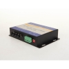
Intelligent CAN to Multi-drop Bus Fiber Optic Converter
Description:
The FO-FIB-100BT CAN bus fiber optic converter provide an optical Multi-drop bus or star network connection for CAN bus data interfaces on one or two, multi mode or single mode optical fibers. The CAN bus fiber optic switch has 1 CAN port and 2 fiber optic ports, CAN port is configurable via software.The CAN bus series units support both CAN 1.0 and CAN 2.0 CAN standards and are transparent to all high level protocols.The converter adopts the latest technology int world, so it can support very high baud rate,very long distance,very complex networks.
Product Features:
- Up to 1Mbps data rate(20km when it’s 1MB,New technology)
- Up to 6500 frames/second,with 1000 frames buffering
- Configurable CAN bus Interface
- Multi mode and single mode
- With buffering
- Single fiber solution supported
- 5 years warranty

Other Specifications:
|
Data |
|
|
Data Formats |
CAN1.0 ,CAN2.0 ,Device Net |
|
CAN Data Rate |
0-1Mbps |
|
Bit Error Rate |
<1 x 10-12 |
|
Connectors |
|
|
Data |
Screw Block Terminal |
|
Fiber |
ST, SC or FC (ST fitted as standard) |
|
Environmental |
|
|
Operating Temperature |
-30C---+70C |
|
Storage Temperature |
-40C---+90C |
|
Operating Humidity |
0-95% |
|
MTBF |
>100,000 Hours |
|
Optical |
|
|
Fiber |
Multi mode or single mode |
|
Wavelength |
850nm/1310nm |
|
Number of fibers |
8 or 4(WDM,Bi-Di) (2TX+2RX) |
|
Power |
|
|
Power Input |
+9-+40V DC |
|
Mechanical |
|
|
Dimensions |
156(W)×108(D)×33.6(H)mm Wall mount
|
Ordering Information:
|
Model Number |
Description |
Port No. |
Fiber Mode |
Fiber Connector |
|
HFD-FO-CAN-P1M |
Fiber Optic Converter,Point to Point Link, Single Fiber(BI-DI), 2km,DIN Rail Mount |
1 CAN +1 FO |
Multi Mode |
ST/SC/FC |
|
HFD-FO-CAN-P2M |
Fiber Optic Converter,Point to Point Link, Dual Fiber, 2km,DIN Rail Mount |
1 CAN+1TX+1RX |
Multi Mode |
ST/SC/FC |
|
HFD-FO-CAN-P1S |
Fiber Optic Converter,Point to Point Link, Single Fiber(BI-DI), 20km |
1 CAN +1 FO |
Single Mode |
ST/SC/FC |
|
HFD-FO-CAN-P2S |
Fiber Optic Converter,Point to Point Link, Dual Fiber, 20km |
1 CAN+1TX+1RX |
Single Mode |
ST/SC/FC |
|
HFD-FO-CAN-M2M |
Fiber Optic Converter,Multi-drop Link, Dual Fiber(BI-DI), 2km |
1 CAN+2 FO |
Multi Mode |
ST/SC/FC |
|
HFD-FO-CAN-M4M |
Fiber Optic Converter,Multi-drop Link, 4 Fiber, 2km |
1 CAN+2TX+2RX |
Multi Mode |
ST/SC/FC |
|
HFD-FO-CAN-M2S |
Fiber Optic Converter,Multi-drop Link, Dual Fiber(BI-DI), 20km |
1 CAN+2 FO |
Single Mode |
ST/SC/FC |
|
HFD-FO-CAN-M4S |
Fiber Optic Converter,Multi-drop Link, 4 Fiber, 20km |
1 CAN+2TX+2RX |
Single Mode |
ST/SC/FC |
|
FO-FIB-100PT |
Configurable Fiber Optic Converter, Point to Point Link,Wall Mount |
1CAN+1TX+1RX |
Single Mode |
ST/SC/FC |
|
FO-FIB-100BT |
Configurable Fiber Optic Converter, Multi Drop Link,Wall Mount |
1CAN+2TX+2RX |
Single Mode |
ST/SC/FC |
|
FO-FIB-MIXED |
Configurable CAN Fiber Optic Switch, Point to point,Multi-drop,Star,Tree, Wall Mount |
2 CAN+2TX+2RX |
Single Mode |
ST/SC/FC |
|
SW-400T |
4 Port Configurable CAN BUS Switch, Wall Mount |
4 CAN |
|
|
|
BRIGE-200T |
Configurable CAN TO CAN Bridge |
2 CAN |
|
|
|
CANET-I |
1 Port CAN to Ethernet Converter |
1 CAN+1 TCP |
|
|
|
CANET-II |
2 Port CAN to Ethernet Converter |
2 CAN+1 TCP |
|
|
|
CAN-USB-I |
1 Port CAN to USB Converter |
1 CAN+1 USB |
|
|
|
CAN-USB-II |
2 Port CAN to USB Converter |
2 CAN+1 USB |
|
|
|
CAN-PCI-5001 |
1 Port CAN PCI Card |
1 CAN+1 PCI |
|
|
|
CAN-PCI-5002 |
2 Port CAN PCI Card |
2 CAN+1 PCI |
|
|
|
CAN-232 |
CAN to RS-232 Converter |
1 CAN+1RS232 |
|
|
|
CAN-485 |
CAN to RS-485 Converter |
1 CAN+1RS485 |
|
|
Configurable CAN to Fiber Optic Converter
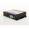
CAN to Fiber Optic Converter(New Technology)
Model: FO-FIB-100PT
Description:
The CAN Bus series products provide an optical point-to-point or bus network connection for CAN bus data interfaces on one or two, multi mode or single mode optical fibers. The CAN Bus Point-to-Point Transmission units operate as the end or terminal points and provide an electrical connection and a two fiber optical connection. The units support CAN 1.0 and CAN 2.0 CAN standards, and Device Net. And are transparent to all high level protocols.It adopts the latest technology in the world,it can be transmitted to 20Km when it's at the baud rate of 1MB(6500 frames).The distance is NOT affected by increased baud rate.
Product Features:
- Up to 1Mbps data rate(Support high rate and long distance transmission)
- Baud rate Configurable,by software and rotary button
- Multi mode and single mode
- Single fiber solution
- Anti-stream: 1000 frames
- Wall mount, rack or chassis configurations
Application:
- Elevator
- Fire control panel
- Industrial automation
- Battery
- Film
- Military defence
- Power substation
- Power plants
| Data | |
| Data Formats | CAN1.0 ,CAN2.0 , Device Net |
| CAN Data Rate | 0-1Mbps |
| Bit Error Rate | <1 x 10-12 |
| Connectors | |
| Data | Screw Block Terminal |
| Fiber | ST, SC or FC (ST fitted as standard) |
| Environmental | |
| Operating Temperat ure | - 3 0 C--- +70 C |
| Storage Temperature | - 40 C--- +85 C |
| Operating Humidity | 0- 95% |
| MTBF | >100,000 Hours |
| Optical | |
| Fiber | Multi mode or single mode |
| Wavelength | MM: 850/1310nm, SM: 1310/1550nm |
| Number of fibers | 2 or 1 |
| POWER | |
| Power Input | +9 to +40V DC |
| Mechanical | |
| Dimensions | 156(W)×108(D)×33.6(H )mm Wall Mount & DIN Rail |
|
Model Number |
Description |
Port No. |
Fiber Mode |
Fiber Connector |
|
HFD-FO-CAN-P1M |
Fiber Optic Converter,Point to Point Link, Single Fiber(BI-DI), 2km,DIN Rail Mount |
1 CAN +1 FO |
Multi Mode |
ST/SC/FC |
|
HFD-FO-CAN-P2M |
Fiber Optic Converter,Point to Point Link, Dual Fiber, 2km,DIN Rail Mount |
1 CAN+1TX+1RX |
Multi Mode |
ST/SC/FC |
|
HFD-FO-CAN-P1S |
Fiber Optic Converter,Point to Point Link, Single Fiber(BI-DI), 20km |
1 CAN +1 FO |
Single Mode |
ST/SC/FC |
|
HFD-FO-CAN-P2S |
Fiber Optic Converter,Point to Point Link, Dual Fiber, 20km |
1 CAN+1TX+1RX |
Single Mode |
ST/SC/FC |
|
HFD-FO-CAN-M2M |
Fiber Optic Converter,Multi-drop Link, Dual Fiber(BI-DI), 2km |
1 CAN+2FO |
Multi Mode |
ST/SC/FC |
|
HFD-FO-CAN-M4M |
Fiber Optic Converter,Multi-drop Link, 4 Fiber, 2km |
1 CAN+2TX+2RX |
Multi Mode |
ST/SC/FC |
|
HFD-FO-CAN-M2S |
Fiber Optic Converter,Multi-drop Link, Dual Fiber(BI-DI), 20km |
1 CAN+2FO |
Single Mode |
ST/SC/FC |
|
HFD-FO-CAN-M4S |
Fiber Optic Converter,Multi-drop Link, 4 Fiber, 20km |
1 CAN+2TX+2RX |
Single Mode |
ST/SC/FC |
|
FO-FIB-100PT |
Configurable Fiber Optic Converter, Point to Point Link,Wall Mount |
1CAN+1TX+1RX |
Single Mode MultiMode |
ST/SC/FC |
|
FO-FIB-100BT |
Configurable Fiber Optic Converter, Multi Drop Link,Wall Mount |
1CAN+2TX+2RX |
Single Mode |
ST/SC/FC |
|
FO-FIB-MIXED |
Configurable CAN Fiber Optic Switch, Point to point,Multi-drop,Star,Tree, Wall Mount |
2 CAN+2TX+2RX |
Single Mode |
ST/SC/FC |
|
SW-400T |
4 Port Configurable CAN BUS Switch, Wall Mount |
4 CAN |
|
|
|
BRIGE-200T |
Configurable CAN TO CAN Bridge |
2 CAN |
|
|
|
CANET-I |
1 Port CAN to Ethernet Converter |
1 CAN+1 TCP |
|
|
|
CANET-II |
2 Port CAN to Ethernet Converter |
2 CAN+1 TCP |
|
|
|
CAN-USB-I |
1 Port CAN to USB Converter |
1 CAN+1 USB |
|
|
|
CAN-USB-II |
2 Port CAN to USB Converter |
2 CAN+1 USB |
|
|
|
CAN-PCI-5001 |
1 Port CAN PCI Card |
1 CAN+1 PCI |
|
|
|
CAN-PCI-5002 |
2 Port CAN PCI Card |
2 CAN+1 PCI |
|
|
|
CAN-232 |
CAN to RS-232 Converter |
1 CAN+1RS232 |
|
|
|
CAN-485 |
CAN to RS-485 Converter |
1 CAN+1RS485 |
|
|
CANbus Fiber Optic Switch(2 Port CAN+2 Port Optical)
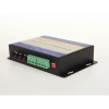
4 Port Intelligent CAN BUS Fiber Optic Switch(Intelligent Router)
Description:
The FO-FIB-MIXED Can bus to fiber optic switch provide an optical point-to-point or bus network connection for Can bus data interfaces on one or two, multimode or single mode optical fibers. The Canbus fiber optic switch has 2 CAN ports and 2 fiber optic ports, all 4 ports are configurable via software.Any port can communicate with other ports,so it has the functions of “Repeater”,”Router” and “Switch”, it can be used in point to point,multi drop bus,star and tree topologies. The Can bus series units support both CAN 1.0 and CAN 2.0B CAN standards and are transparent to all high level protocols.
Product Features:
- All CAN BUS Ports are configurable by software.
- CAN BUS ports can transmit data in different or same baud rate
- Up to 1Mbps data rate(20km when it’s 1MB,New technology)
- Up to 6500 frames/second, with 1000 frames buffering
- All ports can communicate with each other
- Multi mode and single mode
- Point to point,Multi-drop Bus,Star and Tree topologies
- Single fiber solution supported
- 5 years warranty

Specifications:
|
Data |
|
|
Data Formats |
CAN1.0 ,CAN2.0 ,Device Net |
|
CAN Data Rate |
0-1Mbps |
|
Bit Error Rate |
<1 x 10-12 |
|
Connectors |
|
|
Data |
Screw Block Terminal 2 ports |
|
Fiber |
ST, SC or FC (ST fitted as standard) |
|
Environmental |
|
|
Operating Temperature |
-30C---+70C |
|
Storage Temperature |
-40C---+90C |
|
Operating Humidity |
0-95% |
|
MTBF |
>100,000 Hours |
|
Optical |
|
|
Fiber |
Multi mode or single mode |
|
Wavelength |
MM:850nm,SM:1310nm |
|
Number of fibers |
8 or 4(WDM,Bi-Di) (2TX+2RX) |
|
Power |
|
|
Power Input |
+9-+40V DC |
|
Mechanical |
|
|
Dimensions |
156(W)×108(D)×33.6(H)mm Wall mount
|
Ordering Information:
|
Model Number |
Description |
Port No. |
Fiber Mode |
Fiber Connector |
|
HFD-FO-CAN-P1M |
Fiber Optic Converter,Point to Point Link, Single Fiber(BI-DI), 2km,DIN Rail Mount |
1 CAN +1 FO |
Multi Mode |
ST/SC/FC |
|
HFD-FO-CAN-P2M |
Fiber Optic Converter,Point to Point Link, Dual Fiber, 2km,DIN Rail Mount |
1 CAN+1TX+1RX |
Multi Mode |
ST/SC/FC |
|
HFD-FO-CAN-P1S |
Fiber Optic Converter,Point to Point Link, Single Fiber(BI-DI), 20km |
1 CAN +1 FO |
Single Mode |
ST/SC/FC |
|
HFD-FO-CAN-P2S |
Fiber Optic Converter,Point to Point Link, Dual Fiber, 20km |
1 CAN+1TX+1RX |
Single Mode |
ST/SC/FC |
|
HFD-FO-CAN-M2M |
Fiber Optic Converter,Multi-drop Link, Dual Fiber(BI-DI), 2km |
1 CAN+2 FO |
Multi Mode |
ST/SC/FC |
|
HFD-FO-CAN-M4M |
Fiber Optic Converter,Multi-drop Link, 4 Fiber, 2km |
1 CAN+2TX+2RX |
Multi Mode |
ST/SC/FC |
|
HFD-FO-CAN-M2S |
Fiber Optic Converter,Multi-drop Link, Dual Fiber(BI-DI), 20km |
1 CAN+2 FO |
Single Mode |
ST/SC/FC |
|
HFD-FO-CAN-M4S |
Fiber Optic Converter,Multi-drop Link, 4 Fiber, 20km |
1 CAN+2TX+2RX |
Single Mode |
ST/SC/FC |
|
FO-FIB-100PT |
Configurable Fiber Optic Converter, Point to Point Link,Wall Mount |
1CAN+1TX+1RX |
SM/MM |
ST/SC/FC |
|
FO-FIB-100BT |
Configurable Fiber Optic Converter, Multi Drop Link,Wall Mount |
1CAN+2TX+2RX |
SM/MM |
ST/SC/FC |
|
FO-FIB-MIXED |
Configurable CAN Fiber Optic Switch, Point to point,Multi-drop,Star,Tree, Wall Mount |
2 CAN+2TX+2RX |
SM/MM |
ST/SC/FC |
|
SW-400T |
4 Port Configurable CAN BUS Switch, Wall Mount |
4 CAN |
|
|
|
BRIGE-200T |
Configurable CAN TO CAN Bridge |
2 CAN |
|
|
|
CANET-I |
1 Port CAN to Ethernet Converter |
1 CAN+1 TCP |
|
|
|
CANET-II |
2 Port CAN to Ethernet Converter |
2 CAN+1 TCP |
|
|
|
CAN-USB-I |
1 Port CAN to USB Converter |
1 CAN+1 USB |
|
|
|
CAN-USB-II |
2 Port CAN to USB Converter |
2 CAN+1 USB |
|
|
|
CAN-PCI-5001 |
1 Port CAN PCI Card |
1 CAN+1 PCI |
|
|
|
CAN-PCI-5002 |
2 Port CAN PCI Card |
2 CAN+1 PCI |
|
|
|
CAN-232 |
CAN to RS-232 Converter |
1 CAN+1RS232 |
|
|
|
CAN-485 |
CAN to RS-485 Converter |
1 CAN+1RS485 |
|
|
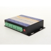
CANbus Fiber Optic Switch(Configurable 4 Port)

4 Port Configurable CAN BUS Fiber Optic Switch(Router)
Description:
The FO-FIB-MIXED Can bus to fiber optic switch provide an optical point-to-point or bus network connection for Can bus data interfaces on one or two, multimode or single mode optical fibers. The Canbus fiber optic switch has 2 CAN ports and 2 fiber optic ports, all 4 ports are configurable via software.Any port can communicate with other ports,so it has the functions of “Repeater”,”Router” and “Switch”, it can be used in point to point,multi drop bus,star and tree topologies. The Can bus series units support both CAN 1.0 and CAN 2.0B CAN standards and are transparent to all high level protocols.
Product Features:
- All CAN BUS Ports are configurable by software.
- CAN BUS ports can transmit data in different or same baud rate
- Up to 1Mbps data rate(20km when it’s 1MB,New technology)
- Up to 6500 frames/second
- Anti-stream: 1000 frames
- All ports can communicate with each other
- Multi mode and single mode
- Point to point,Multi-drop Bus,Star and Tree topologies
- Single fiber solution supported
- 5 years warranty
Specifications:
|
Data |
|
|
Data Formats |
CAN1.0 ,CAN2.0 ,Device Net |
|
CAN Data Rate |
0-1Mbps |
|
Bit Error Rate |
<1 x 10-12 |
|
Connectors |
|
|
Data |
Screw Block Terminal 2 ports |
|
Fiber |
ST, SC or FC (ST fitted as standard) |
|
Environmental |
|
|
Operating Temperature |
-30C---+70C |
|
Storage Temperature |
-40C---+90C |
|
Operating Humidity |
0-95% |
|
MTBF |
>100,000 Hours |
|
Optical |
|
|
Fiber |
Multi mode or single mode |
|
Wavelength |
MM:850nm,SM:1310nm |
|
Number of fibers |
4 or 2(WDM,Bi-Di) (2TX+2RX) |
|
Power |
|
|
Power Input |
+9-+40V DC |
|
Mechanical |
|
|
Dimensions |
156(W)×108(D)×33.6(H)mm Wall mount
|
Ordering Information:
|
Model Number |
Description |
Port No. |
Fiber Mode |
Fiber Connector |
|
HFD-FO-CAN-P1M |
Fiber Optic Converter,Point to Point Link, Single Fiber(BI-DI), 2km,DIN Rail Mount |
1 CAN +1 FO |
Multi Mode |
ST/SC/FC |
|
HFD-FO-CAN-P2M |
Fiber Optic Converter,Point to Point Link, Dual Fiber, 2km,DIN Rail Mount |
1 CAN+1TX+1RX |
Multi Mode |
ST/SC/FC |
|
HFD-FO-CAN-P1S |
Fiber Optic Converter,Point to Point Link, Single Fiber(BI-DI), 20km |
1 CAN +1 FO |
Single Mode |
ST/SC/FC |
|
HFD-FO-CAN-P2S |
Fiber Optic Converter,Point to Point Link, Dual Fiber, 20km |
1 CAN+1TX+1RX |
Single Mode |
ST/SC/FC |
|
HFD-FO-CAN-M2M |
Fiber Optic Converter,Multi-drop Link, Dual Fiber(BI-DI), 2km |
1 CAN+2 FO |
Multi Mode |
ST/SC/FC |
|
HFD-FO-CAN-M4M |
Fiber Optic Converter,Multi-drop Link, 4 Fiber, 2km |
1 CAN+2TX+2RX |
Multi Mode |
ST/SC/FC |
|
HFD-FO-CAN-M2S |
Fiber Optic Converter,Multi-drop Link, Dual Fiber(BI-DI), 20km |
1 CAN+2 FO |
Single Mode |
ST/SC/FC |
|
HFD-FO-CAN-M4S |
Fiber Optic Converter,Multi-drop Link, 4 Fiber, 20km |
1 CAN+2TX+2RX |
Single Mode |
ST/SC/FC |
|
FO-FIB-100PT |
Configurable Fiber Optic Converter, Point to Point Link,Wall Mount |
1CAN+1TX+1RX |
SM/MM |
ST/SC/FC |
|
FO-FIB-100BT |
Configurable Fiber Optic Converter, Multi Drop Link,Wall Mount |
1CAN+2TX+2RX |
SM/MM |
ST/SC/FC |
|
FO-FIB-MIXED |
Configurable CAN Fiber Optic Switch, Point to point,Multi-drop,Star,Tree, Wall Mount |
2 CAN+2TX+2RX |
SM/MM |
ST/SC/FC |
|
SW-400T |
4 Port Configurable CAN BUS Switch, Wall Mount |
4 CAN |
|
|
|
BRIGE-200T |
Configurable CAN TO CAN Bridge |
2 CAN |
|
|
|
CANET-I |
1 Port CAN to Ethernet Converter |
1 CAN+1 TCP |
|
|
|
CANET-II |
2 Port CAN to Ethernet Converter |
2 CAN+1 TCP |
|
|
|
CAN-USB-I |
1 Port CAN to USB Converter |
1 CAN+1 USB |
|
|
|
CAN-USB-II |
2 Port CAN to USB Converter |
2 CAN+1 USB |
|
|
|
CAN-PCI-5001 |
1 Port CAN PCI Card |
1 CAN+1 PCI |
|
|
|
CAN-PCI-5002 |
2 Port CAN PCI Card |
2 CAN+1 PCI |
|
|
|
CAN-232 |
CAN to RS-232 Converter |
1 CAN+1RS232 |
|
|
|
CAN-485 |
CAN to RS-485 Converter |
1 CAN+1RS485 |
|
|
CAN Bus Switch
4 Port Manageable CAN BUS Switch(CAN Router)
Description of CAN Bus Switch:
The SW-400T CAN Bus Switch is a new CAN bus switch that combined the world's most advanced technology into it. There are 4 independent CAN channels who can communicate with each other with different or same baud rates. This new topology could resolve the complex CAN bus application, like industrial automation, building automation, Alarm System,ITS, and etc. The SW-400T CAN switch can run to 6000 to 6500 frames/second and it has buffering to ensure the reliability of the CAN data transmission. It helps users to extend the CAN network system. The SW-400T comes with configurable software and UART console port.
Product Features of CANbus Switch:
- 4 CAN bus ports(Configurable)
- Compatible with CAN specification 2.0A and 2.0B
- Fully compatible with the ISO 11898-2 standard
- Baud rate : 0-1MB, Can be configured by software
- CAN bus filter is configurable
- 1500 data frames buffer for each CAN channel
- Max data flow up to 6500 frames in total
- Selectable baud rate by rotary switch
- Selectable 120Ω terminator resistor by DIP switch
- LED for CAN reception and transmission
- Support CAN network with star or tree topology
- Different baud rates can communicate in the switch
Other Specifications of CAN Bus Switch:
Hardware
Controller High Performance Microcontroller
CAN Interface
CAN: 4 Ports Block terminal connector
CAN Standard: ISO-11898-2, CAN 2.0A and CAN 2.0B
Baud Rate (bps): 0-1MB
Baud Rate Setting up: By rotary switch
Isolation 3000 VDC for DC-to-DC, 2500 Vrms for photo-couple
Terminator Resistor Selectable 120Ω terminator resistor by internal jump
Transmission Distance (m) Depend on baud rate (for example, max. 1000 m at 50 kbps )
CAN Filter Configurable by user
Console Interface
RS-232 1 port (for configuration)
Power
Input range Unregulated +9 ~ +40 VDC
Power Consumption 1.5W
Mechanism
Installation Wall-Mounting
Casing Aluminum metallic case
Dimensions 156 x 108 x 33.6 mm (WxDxH)
Environment
Operating Temp. -30 ~ 80 ℃
Storage Temp. -35 ~ 90 ℃
Humidity 10 ~ 95% RH, non-condensing
ESD protection 10 kV Contact for each channel
EFT protection 500V for signal, 1000V for power
Application of the CAN Bus Switch:
ITS,Power automation,Industrial Automation,Fire Alarm System,Lift control,etc.

Ordering Information:
|
Model Number |
Description |
Port No. |
Fiber Mode |
Fiber Connector |
|
HFD-FO-CAN-P1M |
Fiber Optic Converter,Point to Point Link, Single Fiber(BI-DI), 2km,DIN Rail Mount |
1 CAN +1 FO |
Multi Mode |
ST/SC/FC |
|
HFD-FO-CAN-P2M |
Fiber Optic Converter,Point to Point Link, Dual Fiber, 2km,DIN Rail Mount |
1 CAN+1TX+1RX |
Multi Mode |
ST/SC/FC |
|
HFD-FO-CAN-P1S |
Fiber Optic Converter,Point to Point Link, Single Fiber(BI-DI), 20km |
1 CAN +1 FO |
Single Mode |
ST/SC/FC |
|
HFD-FO-CAN-P2S |
Fiber Optic Converter,Point to Point Link, Dual Fiber, 20km |
1 CAN+1TX+1RX |
Single Mode |
ST/SC/FC |
|
HFD-FO-CAN-M2M |
Fiber Optic Converter,Multi-drop Link, Dual Fiber(BI-DI), 2km |
1 CAN+2 FO |
Multi Mode |
ST/SC/FC |
|
HFD-FO-CAN-M4M |
Fiber Optic Converter,Multi-drop Link, 4 Fiber, 2km |
1 CAN+2TX+2RX |
Multi Mode |
ST/SC/FC |
|
HFD-FO-CAN-M2S |
Fiber Optic Converter,Multi-drop Link, Dual Fiber(BI-DI), 20km |
1 CAN+2 FO |
Single Mode |
ST/SC/FC |
|
HFD-FO-CAN-M4S |
Fiber Optic Converter,Multi-drop Link, 4 Fiber, 20km |
1 CAN+2TX+2RX |
Single Mode |
ST/SC/FC |
|
FO-FIB-100PT |
Configurable Fiber Optic Converter, Point to Point Link,Wall Mount |
1CAN+1TX+1RX |
Single Mode |
ST/SC/FC |
|
FO-FIB-100BT |
Configurable Fiber Optic Converter, Multi Drop Link,Wall Mount |
1CAN+2TX+2RX |
Single Mode |
ST/SC/FC |
|
FO-FIB-MIXED |
Configurable CAN Fiber Optic Switch, Point to point,Multi-drop,Star,Tree, Wall Mount |
2 CAN+(2TX+2RX) |
Single Mode |
ST/SC/FC |
|
SW-400T |
4 Port Configurable CAN BUS Switch, Wall Mount |
4 CAN |
|
|
|
BRIGE-200T |
Configurable CAN TO CAN Bridge |
2 CAN |
|
|
|
CANET-I |
1 Port CAN to Ethernet Converter |
1 CAN+1 TCP |
|
|
|
CANET-II |
2 Port CAN to Ethernet Converter |
2 CAN+1 TCP |
|
|
|
CAN-USB-I |
1 Port CAN to USB Converter |
1 CAN+1 USB |
|
|
|
CAN-USB-II |
2 Port CAN to USB Converter |
2 CAN+1 USB |
|
|
|
CAN-PCI-5001 |
1 Port CAN PCI Card |
1 CAN+1 PCI |
|
|
|
CAN-PCI-5002 |
2 Port CAN PCI Card |
2 CAN+1 PCI |
|
|
|
CAN-232 |
CAN to RS-232 Converter |
1 CAN+1RS232 |
|
|
|
CAN-485 |
CAN to RS-485 Converter |
1 CAN+1RS485 |
|
|
The Advantage of Smart Power Meter
Smart Power meter is the smart grid construction, electric power customer electricity information collection system construction is the most basic unit, smart meters change is closely related to the power of the families. At present most of the customers to use electricity in our province of power meter is single function of the more common electronic watt-hour meter, no communication function or communication mouth damage, is now can not meet the national construction of smart grid, smart electricity and the need of power remote automatic information acquisition, and most of the service life of power meter is about to reach its installation, according to the requirements of relevant national laws and regulations, should rotate new power meter.
Install the smart power meter advantages:
1) Make life more convenient. Intelligent power meter can be realized through the acquisition system of automatic meter reading, improve the meter accuracy, reduce the disturb for customers.
2) Users can real-time understand their electricity through electric power company website.
3) Make life more low carbon. Smart power meter can be both electricity and sell electricity twofold measurement attributes. Such as: can link to a small family and devices, such as wind power and photovoltaic roof so as to raise the proportion of clean energy consumption, reduce the pollution of the city.
4) Make life more economical. Smart power meter support time-sharing electricity prices, ladder electricity price and electricity price policy implementation, can help customers to choose the way of electricity, save energy, reduce the energy expense. By the calculation, when customers choose and optimize the utilization way actively, can reduce more than 15% of the peak load and more than 10% of the total demand.
The electromagnetic radiation:
Please rest assured, won't produce power facilities called \"electromagnetic radiation\", will not cause harm to human body. Electromagnetic radiation is a physical phenomenon, refers to the spread of the energy in the form of high frequency electromagnetic waves in space. Three-phase AC power system in our country are used in 50 hz, the wavelength of 6000 km, the electromagnetic field can't alternation in the form of electromagnetic wave propagation in space, do not produce electromagnetic radiation. In the international authority file, the electric field and magnetic field caused by ac transmission facilities have been explicitly referred to as the power frequency electric field and magnetic field, power frequency and not according to electromagnetic radiation, and the power frequency magnetic induction intensity is very low. Now, for example, three of the most common voltage grade 110, 220, 500 kv transmission line on the ground of 1.5 meters above the power frequency magnetic induction intensity is far less than 100, equivalent to the distance of 3 cm microwave power frequency magnetic induction intensity of 1/2. Substation station bound 1 meter outside the power frequency magnetic induction intensity of less than 10 micro, TV set, washing machine power frequency is equal to the distance 3 cm 1/5 of the magnetic induction intensity, and far below the recommended limit prescribed by the 0.1 mm (mT).
Distributed Control System(DCS)
A distributed control system (DCS) refers to a control system usually of a manufacturing system[clarification needed], process or any kind of dynamic system, in which the controller elements are not central in location (like the brain) but are distributed throughout the system with each component sub-system controlled by one or more controllers.
DCS (Distributed Control System) is a computerized control system used to control the production line in the industry
The entire system of controllers is connected by networks for communication and monitoring.
DCS is a very broad term used in a variety of industries, to monitor and control distributed equipment.
Electrical power grids and electrical generation plants
Environmental control systems
Traffic signals
Radio signals
Water management systems
Oil refining plants
Metallurgical process plants
Chemical plants
Pharmaceutical manufacturing
Sensor networks
Dry cargo and bulk oil carrier ships
Elements
A DCS typically uses custom designed processors as controllers and uses both proprietary interconnections and communications protocol for communication. Input and output modules form component parts of the DCS. The processor receives information from input modules and sends information to output modules. The input modules receive information from input instruments in the process (or field) and transmit instructions to the output instruments in the field. Computer buses or electrical buses connect the processor and modules through multiplexer or demultiplexers. Buses also connect the distributed controllers with the central controller and finally to the Human–machine interface (HMI) or control consoles. See Process automation system.
The elements of a DCS may connect directly to physical equipment such as switches, pumps and valves and to Human Machine Interface (HMI) via SCADA. The differences between a DCS and SCADA is often subtle, especially with advances in technology allowing the functionality of each to overlap.[1]
Applications
Distributed control systems (DCSs) are dedicated systems used to control manufacturing processes that are continuous or batch-oriented, such as oil refining, petrochemicals, central station power generation, fertilizers, pharmaceuticals, food and beverage manufacturing, cement production, steelmaking, and papermaking. DCSs are connected to sensors and actuators and use setpoint control to control the flow of material through the plant. The most common example is a setpoint control loop consisting of a pressure sensor, controller, and control valve. Pressure or flow measurements are transmitted to the controller, usually through the aid of a signal conditioning input/output (I/O) device. When the measured variable reaches a certain point, the controller instructs a valve or actuation device to open or close until the fluidic flow process reaches the desired setpoint. Large oil refineries have many thousands of I/O points and employ very large DCSs. Processes are not limited to fluidic flow through pipes, however, and can also include things like paper machines and their associated quality controls (see quality control system QCS), variable speed drives and motor control centers, cement kilns, mining operations, ore processing facilities, and many others.
A typical DCS consists of functionally and/or geographically distributed digital controllers capable of executing from 1 to 256 or more regulatory control loops in one control box. The input/output devices (I/O) can be integral with the controller or located remotely via a field network. Today’s controllers have extensive computational capabilities and, in addition to proportional, integral, and derivative (PID) control, can generally perform logic and sequential control. Modern DCSs also support neural networks and fuzzy application.
DCS systems are usually designed with redundant processors to enhance the reliability of the control system. Most systems come with canned displays and configuration software which enables the end user to set up the control system without a lot of low level programming. This allows the user to better focus on the application rather than the equipment, although a lot of system knowledge and skill is still required to support the hardware and software as well as the applications. Many plants have dedicated groups that focus on this task. These groups are in many cases augmented by vendor support personnel and/or maintenance support contracts.
DCSs may employ one or more workstations and can be configured at the workstation or by an off-line personal computer. Local communication is handled by a control network with transmission over twisted pair, coaxial, or fiber optic cable. A server and/or applications processor may be included in the system for extra computational, data collection, and reporting capability.
History
Early minicomputers were used in the control of industrial processes since the beginning of the 1960s. The IBM 1800, for example, was an early computer that had input/output hardware to gather process signals in a plant for conversion from field contact levels (for digital points) and analog signals to the digital domain.
The first industrial control computer system was built 1959 at the Texaco Port Arthur, Texas, refinery with an RW-300 of the Ramo-Wooldridge Company[2]
The DCS was introduced in 1975. Both Honeywell and Japanese electrical engineering firm Yokogawa introduced their own independently produced DCSs at roughly the same time, with the TDC 2000 and CENTUM[3] systems, respectively. US-based Bristol also introduced their UCS 3000 universal controller in 1975. In 1978 Metso(known as Valmet in 1978) introduced their own DCS system called Damatic (latest generation named Metso DNA[4]). In 1980, Bailey (now part of ABB[5]) introduced the NETWORK 90 system. Also in 1980, Fischer & Porter Company (now also part of ABB[6]) introduced DCI-4000 (DCI stands for Distributed Control Instrumentation).
The DCS largely came about due to the increased availability of microcomputers and the proliferation of microprocessors in the world of process control. Computers had already been applied to process automation for some time in the form of both direct digital control (DDC) and set point control. In the early 1970s Taylor Instrument Company, (now part of ABB) developed the 1010 system, Foxboro the FOX1 system and Bailey Controls the 1055 systems. All of these were DDC applications implemented within minicomputers (DEC PDP-11, Varian Data Machines, MODCOMP etc.) and connected to proprietary Input/Output hardware. Sophisticated (for the time) continuous as well as batch control was implemented in this way. A more conservative approach was set point control, where process computers supervised clusters of analog process controllers. A CRT-based workstation provided visibility into the process using text and crude character graphics. Availability of a fully functional graphical user interface was a way away.
Central to the DCS model was the inclusion of control function blocks. Function blocks evolved from early, more primitive DDC concepts of "Table Driven" software. One of the first embodiments of object-oriented software, function blocks were self-contained "blocks" of code that emulated analog hardware control components and performed tasks that were essential to process control, such as execution of PID algorithms. Function blocks continue to endure as the predominant method of control for DCS suppliers, and are supported by key technologies such as Foundation Fieldbus[7] today.
Midac Systems, of Sydney, Australia, developed an objected-oriented distributed direct digital control system in 1982. The central system ran 11 microprocessors sharing tasks and common memory and connected to a serial communication network of distributed controllers each running two Z80s. The system was installed at the University of Melbourne.[citation needed]
Digital communication between distributed controllers, workstations and other computing elements (peer to peer access) was one of the primary advantages of the DCS. Attention was duly focused on the networks, which provided the all-important lines of communication that, for process applications, had to incorporate specific functions such as determinism and redundancy. As a result, many suppliers embraced the IEEE 802.4 networking standard. This decision set the stage for the wave of migrations necessary when information technology moved into process automation and IEEE 802.3 rather than IEEE 802.4 prevailed as the control LAN.
The Network Centric Era of the 1980s
In the 1980s, users began to look at DCSs as more than just basic process control. A very early example of a Direct Digital Control DCS was completed by the Australian business Midac in 1981–82 using R-Tec Australian designed hardware. The system installed at the University of Melbourne used a serial communications network, connecting campus buildings back to a control room "front end". Each remote unit ran 2 Z80 microprocessors whilst the front end ran 11 in a Parallel Processing configuration with paged common memory to share tasks and could run up to 20,000 concurrent controls objects.
It was believed that if openness could be achieved and greater amounts of data could be shared throughout the enterprise that even greater things could be achieved. The first attempts to increase the openness of DCSs resulted in the adoption of the predominant operating system of the day: UNIX. UNIX and its companion networking technology TCP-IP were developed by the US Department of Defense for openness, which was precisely the issue the process industries were looking to resolve.
As a result suppliers also began to adopt Ethernet-based networks with their own proprietary protocol layers. The full TCP/IP standard was not implemented, but the use of Ethernet made it possible to implement the first instances of object management and global data access technology. The 1980s also witnessed the first PLCs integrated into the DCS infrastructure. Plant-wide historians also emerged to capitalize on the extended reach of automation systems. The first DCS supplier to adopt UNIX and Ethernet networking technologies was Foxboro, who introduced the I/A Series[8] system in 1987.
The application-centric era of the 1990s[edit]The drive toward openness in the 1980s gained momentum through the 1990s with the increased adoption of commercial off-the-shelf (COTS) components and IT standards. Probably the biggest transition undertaken during this time was the move from the UNIX operating system to the Windows environment. While the realm of the real time operating system (RTOS) for control applications remains dominated by real time commercial variants of UNIX or proprietary operating systems, everything above real-time control has made the transition to Windows.
The introduction of Microsoft at the desktop and server layers resulted in the development of technologies such as OLE for process control (OPC), which is now a de facto industry connectivity standard. Internet technology also began to make its mark in automation and the DCS world, with most DCS HMI supporting Internet connectivity. The 1990s were also known for the "Fieldbus Wars", where rival organizations competed to define what would become the IEC fieldbus standard for digital communication with field instrumentation instead of 4–20 milliamp analog communications. The first fieldbus installations occurred in the 1990s. Towards the end of the decade, the technology began to develop significant momentum, with the market consolidated around Ethernet I/P, Foundation Fieldbus and Profibus PA for process automation applications. Some suppliers built new systems from the ground up to maximize functionality with fieldbus, such as Rockwell PlantPAX System, Honeywell with Experion & Plantscape SCADA systems, ABB with System 800xA,[9] Emerson Process Management[10] with the Emerson Process Management DeltaV control system, Siemens with the SPPA-T3000 [11] or Simatic PCS 7[12] and Azbil Corporation[13] with the Harmonas-DEO system. Fieldbus technics have been used to integrate machine, drives, quality and condition monitoring applications to one DCS with Metso DNA system.[4]
The impact of COTS, however, was most pronounced at the hardware layer. For years, the primary business of DCS suppliers had been the supply of large amounts of hardware, particularly I/O and controllers. The initial proliferation of DCSs required the installation of prodigious amounts of this hardware, most of it manufactured from the bottom up by DCS suppliers. Standard computer components from manufacturers such as Intel and Motorola, however, made it cost prohibitive for DCS suppliers to continue making their own components, workstations, and networking hardware.
As the suppliers made the transition to COTS components, they also discovered that the hardware market was shrinking fast. COTS not only resulted in lower manufacturing costs for the supplier, but also steadily decreasing prices for the end users, who were also becoming increasingly vocal over what they perceived to be unduly high hardware costs. Some suppliers that were previously stronger in the PLC business, such as Rockwell Automation and Siemens, were able to leverage their expertise in manufacturing control hardware to enter the DCS marketplace with cost effective offerings, while the stability/scalability/reliability and functionality of these emerging systems are still improving. The traditional DCS suppliers introduced new generation DCS System based on the latest Communication and IEC Standards, which resulting in a trend of combining the traditional concepts/functionalities for PLC and DCS into a one for all solution—named "Process Automation System". The gaps among the various systems remain at the areas such as: the database integrity, pre-engineering functionality, system maturity, communication transparency and reliability. While it is expected the cost ratio is relatively the same (the more powerful the systems are, the more expensive they will be), the reality of the automation business is often operating strategically case by case. The current next evolution step is called Collaborative Process Automation Systems.
To compound the issue, suppliers were also realizing that the hardware market was becoming saturated. The lifecycle of hardware components such as I/O and wiring is also typically in the range of 15 to over 20 years, making for a challenging replacement market. Many of the older systems that were installed in the 1970s and 1980s are still in use today, and there is a considerable installed base of systems in the market that are approaching the end of their useful life. Developed industrial economies in North America, Europe, and Japan already had many thousands of DCSs installed, and with few if any new plants being built, the market for new hardware was shifting rapidly to smaller, albeit faster growing regions such as China, Latin America, and Eastern Europe.
Because of the shrinking hardware business, suppliers began to make the challenging transition from a hardware-based business model to one based on software and value-added services. It is a transition that is still being made today. The applications portfolio offered by suppliers expanded considerably in the '90s to include areas such as production management, model-based control, real-time optimization, plant asset management (PAM), Real-time performance management (RPM) tools, alarm management, and many others. To obtain the true value from these applications, however, often requires a considerable service content, which the suppliers also provide.
New No-cascading Devicenet Fiber Optic Converters Used in Norway Gas Transmission Project
The debut of new model of DeviceNet fiber optic converter attracted many customers' eye,including a Norwegian Gas transmission project which uses 50 pieces of converters to embed into the data acquisition system.The new DeviceNet fiber optic converters is invented by Bueno team who adopts the most advanced technology in the world.The customer wants to transmit DeviceNet data to more than 6km,which can not be achieved by traditional products due to the cascading problem of DeviceNet when it's on long distance.Bueno solved all these problems and can ensure the converter work in good condition even when it's at high rate and very long distance.
Methods of Smart Grid Deployment Increase
Many professionals in the energy industry agree that the county's electric grid needs to be modernized but there are a number of questions as to how.
The country's power landscape is changing, but it needs an electrical infrastructure to change along with it. Cybersecurity threats across networks are increasing, as most recently shown by the hacking of the New York Times website, while transmission and distribution reliability is not keeping up with the growing demand for power across the country.
There is a growing chorus in the energy business who believe that the answers to these questions come from the ability to develop a smart grid, that is governed by greater control and communication. While the technologies that can enable this kind of grid are improving quickly, their adoption has not been nearly as rapid. For this reason many people are looking for ways in which smart grid technology can become more of a mainstay.
Smart grid forum
A story by Smart Grid News explains that two groups - the Advanced Energy Economy and the Massachusetts Institute of Technology's Industrial Performance Center - recently held their third forum in an attempt to find solutions to increase smart grid deployment by bringing people together from different sectors within the industry.
The challenges they faced are numerous given that it combines elements of business, industry growth and technological development. The news source explains that a series of goals emerged from the discussions that revolve around creating business models that can help support wider deployment, retail services that can meet customer demands, mobilizing funds to be able to do so and the development of a cohesive strategy across sectors.
California deployment
One way utilities are advancing smart grid deployment is through the utilization of technology that can help integrate renewable energy into the country's established electrical infrastructure. The need for this technology is becoming increasingly necessary as alternative power sources, like solar energy, grow in prominence.
A story on the Optics website explains that this is especially true in California, where the state hopes to have about a third of its energy come from renewable sources by 2020. For this reason, utilities in the region are looking to roll-out technology that is able to increase communication and control across the grid so that the introduction of these new power sources is more seamless.
One way companies are doing this is through the use of big data on the grid. For example, intelligent electronic devices can measure and manage grid activity along different points of a company's infrastructure.
Energy Management System(EMS)
An energy management system (EMS) is a system of computer-aided tools used by operators of electric utility grids to monitor, control, and optimize the performance of the generation and/or transmission system. The monitor and control functions are known as SCADA; the optimization packages are often referred to as "advanced applications".
The computer technology is also referred to as SCADA/EMS or EMS/SCADA. In these respects, the terminology EMS then excludes the monitoring and control functions, but more specifically refers to the collective suite of power network applications and to the generation control and scheduling applications.
Manufacturers of EMS also commonly supply a corresponding dispatcher training simulator (DTS). This related technology makes use of components of SCADA and EMS as a training tool for control centre operators. It is also possible to acquire an independent DTS from a non-EMS source such as EPRI
Energy management systems are also often commonly used by individual commercial entities to monitor, measure, and control their electrical building loads. Energy management systems can be used to centrally control devices like HVAC units and lighting systems across multiple locations, such as retail, grocery and restaurant sites. Energy management systems can also provide metering, submetering, and monitoring functions that allow facility and building managers to gather data and insight that allows them to make more informed decisions about energy activities across their sites.
Operating systems
Up to the early 1990s, it was common to find EMS systems being delivered based on proprietary hardware and operating systems. Back then EMS suppliers such as Harris Controls (now GE), Hitachi, Cebyc, Siemens and Toshiba manufactured their own proprietary hardware. EMS suppliers that did not manufacture their own hardware often relied on products developed by Digital Equipment, Gould Electronics and MODCOMP. The VAX 11/780 from Digital Equipment was a popular choice amongst some EMS suppliers. EMS systems such as ETAP now rely on a model based approach. Traditional planning models and EMS models were always independently maintained and seldom in synchronism with each other. Using EMS software like ETAP allows planners and operators to share a common model reducing the mismatch between the two and cutting model maintenance by half. Having a common user interface also allows for easier transition of information from planning to operations.
As proprietary systems became uneconomical, EMS suppliers began to deliver solutions based on industry standard hardware platforms such as those from Digital Equipment (later Compaq), HP, IBM and Sun. The common operating system then was either DEC OpenVMS or UNIX. By 2004, various EMS suppliers including Areva, ABB and OSI had begun to offer Windows based solutions. By 2006 customers had a choice of UNIX, Linux or Windows-based systems. Some suppliers including NARI, PSI-CNI and Siemens continue to offer UNIX-based solutions. It is now common for suppliers to integrate UNIX-based solutions on either the Sun Solaris or IBM platform. Newer EMS systems based on blade servers occupy a fraction of the space previously required. For instance, a blade rack of 20 servers occupy much the same space as that previously occupied by a single MicroVAX server.
Other meanings
Energy efficiency
In a slightly different context EMS can also refer to a system in an organization to achieve energy efficiency through well laid out procedures and methods, and to ensure continual improvement, which will spread awareness of energy efficiency throughout an entire organisation.
Automated control of building energy
The term Energy Management System can also refer to a computer system which is designed specifically for the automated control and monitoring of those electromechanical facilities in a building which yield significant energy consumption such as heating, ventilation and lighting installations. The scope may span from a single building to a group of buildings such as university campuses, office buildings, retail stores networks or factories. Most of these energy management systems also provide facilities for the reading of electricity, gas and water meters. The data obtained from these can then be used to perform self-diagnostic and optimization routines on a frequent basis and to produce trend analysis and annual consumption forecasts.