Sidebar
News Press

Administrator
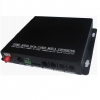
16 Port Serial Device Server
16 Port Serial Device Server(Designed for Power Automation)
Overview
The SED16 device servers are designed to make serial devices network-ready in an instant and give your PC software direct access to serial devices from anywhere on the network. The SED16 device servers are ultra lean, ruggedized, and user friendly, making simple and reliable serial to Ethernet solutions possible.
Features and Benefits
· World’s lowest power consumption
· Speedy 3-step web-based configuration
· Surge protection for serial, Ethernet, and power lines
· COM port grouping and UDP multicast applications
· Screw connectors for secure installation
· DC power inputs with terminal block
· Versatile TCP and UDP operation modes
A Greener Serial-to-Ethernet Solution
The SED16 is a small but powerful ARM-based serial-to-Ethernet SoC with RAM and Flash embedded. With the ARM9 inside, the SED16 series becomes the lowest power consumption device server in the world. The SED16 series saves at least 50% on power consumption compared to existing solutions on the market, helping engineers meet the tough environmental compliance challenges found in today’s industrial environments.
3-step Web-based Configuration
The SED16’s 3-step web-based configuration tool is straightforward and user-friendly. The SED16’s web console guides users through 3 simple configuration steps that are necessary to activate the serial-to-Ethernet application. With this speedy 3-step web-based configuration, a user only needs to spend an average of 30 seconds to complete the settings and enable the application, saving a great amount of time and effort.
COM Port Grouping
The SED16’s COM Grouping function allows you to create a COM Group and redirect data from it to several physical COM ports on device servers. With COM Grouping, you will be able to control multiple physical serial ports simultaneously by operating only one COM port.
The SED16 series can conveniently connect up to 8 serial devices to an Ethernet, allowing you to network your existing serial devices with only basic configuration. With SED16 series, you can both centralize the management of your serial devices, and distribute management hosts over the network. SED16 series can be used to connect different devices for remote management, each serial port operates independently to provide maximum versatility, each port can be operate in Driver, TCP Server, and TCP Client mode independently.
Features:
1. Adopt 32 bit ARM processor
2. 8 serial ports, with support for RS-232/RS-485/RS-422
3. Support 10/100M Ethernet
4. Support 300bps-115.2Kbps
5. Support TCP, ICMP,IP,DHCP,BOOTP,DNS,SNMP V1,HTTP,SMTP,SNTP,PPP,SLIP,UDP, ARP, ICMP, HTTP, TELNET and DHCP protocols. Support across gateway, router communication
7. Support standard TCP/IP SOCKET
8. Support Virtual serial driver access and auto connect after the network disconnect
9. Choice of configuration methods: Windows, TELNET and WEB
10. Support DIN-Rail or wall mounting installation
Specifications:
Ethernet
Number of ports:2
Standard:10/100Base-T(X)
Speed:10/100M auto-sensing
Working mode: half /full duplex
Working: TCP Server, TCP Client, UDP and Real COM driver
Memory: 8M RAM,4M flash
Electromagnetism isolate: 1.5KV
Connector: RJ45
Serial
Standard:RS-232/RS-485
Number of ports: 16
Signals: RS-232:DCD,RXD,TXD,DTR,GND,DSR,RTS,CTS
RS-485:Data+,Data-,GND
RS-422:TXD+,TXD-,RXD+,RXD-,GND
Parity: None, Even, Odd, Space, Mark
Data bits: 5bit, 6bit, 7bit, 8bit
Stop bits: 1, 1.5, 2
Baud rate: 300bps ~ 115.2Kbps
Flow control: RTS/CTS or XON/XOFF
Direction control: RS485 side adopt ADDC technology, auto text and control data transfer direction
Loading: RS-485/422 side support 32 nodes (customize 128 nodes) loopback
Transmission: RS-485/422 side 1200M,
RS-232 port 15M
Interface protection:600W surge protection,
15KV ESD protection
Software
Network protocols: Support TCP, ICMP,IP,DHCP,BOOTP,DNS,SNMP V1,HTTP,SMTP,SNTP,,PPP,SLIP,UDP, ARP, ICMP, HTTP, TELNET and DHCP protocol
Driver support: Windows Real COM driver(Windows NT/2000, Windows XP/2003)
Configuration options: Windows, TELNET and WEB
Power
Power input: 9-40VDC or other AC input
Consumption: <2.5W
Environment
Working temperature:-20°C~60°C
Storage temperature:-25°C~85°C
Humidity: Relative humidity 5% to 95%
Appearance
Color: Black
54*121*200mm(1U Enclosure)
Material: Iron (Housing)
The connection way may combine willfully ,serial connector can be termial mark or RJ45 conncetor.
Safety: EN 60950-1
EMC: CE, FCC
GB/T 17626.2-2006 Class 4
GB/T 17626.4-2008 Class 4
GB/T 17626.5-2008 Class 4
GB/T 17626.6-2008 Class 3
EMI: EN 55022 Class A, FCC Part 15 Subpart B Class A
EMS: EN 55024
Power Line Protection:
EN 61000-4-4(EFT) Level 2,
EN 61000-4-5(Surge) Level 3
Warranty: 5 Years
Warranty Statement
Warranty Time & Terms:
Bueno Electric products are warranted to be free from manufacturing defects in materials and workmanship starting from the shipping date. The warranty period of all network and protection replay products is 5 years.
Product warranties remain valid provided the product was properly installed and used. Defects, malfunctions, or failures of the warranted product caused by damage resulting from Force Majeure (such as floods, fire, etc.), environmental and atmospheric disturbances, other external forces such as power line disturbances, malfunction, plugging the board in under power, or incorrect cabling, and damage caused by misuse, abuse, and unauthorized alteration or repair, are not warranted.
This warranty is limited to the repair and/or replacement, at Bueno Electric's sole discretion, of the defective product during its warranty period. Bueno Electric will replace any product found to be defective within the first three months from the shipping date of Bueno Electric said product was properly installed and used. The customer must obtain a Return Merchandise Authorization (RMA) number prior to returning the defective product to Bueno Electric for service.
The customer agrees to insure the product or assume the risk of loss or damage during transit, to prepay shipping charges, and to use the original shipping container or equivalent. Repaired or replaced products are warranted for ninety (90) days from the date of repair or replacement, or for the remainder of the original product's warranty period, whichever is longer.
For large order projects, customers may purchase a post-warranty repair service. Such products may have a shorter chipset life cycle, or some parts may have a limited warranty from the original supplier of the parts. Please contact Bueno Electric's sales department if you would like to have this service.
Limitation of Liability:
The provisions of the warranty are in lieu of any other warranty, whether expressed or implied, written or oral. Bueno Electric's liability arising out of the manufacture, sale, or supplying of the product and its use, whether based on warranty, contract, negligence, product liability, or otherwise, shall not exceed the original cost of the product. In no event shall Bueno Electric be liable for unintended or consequential damages, including, but not limited to, a loss of profits or use damages arising out of the manufacture, sale, or supplying of the product.
Digital Remote Tripping Judgement Device
BPT003 Series
Digital Remote Tripping Judgement Device
1 Introductions
BPT003 is digital remote tripping local judgment series device based on 32-bit microprocessor,it also has functions of over voltage protection, and over voltage send signal to start remote tripping.
1.1 Application scope
Over voltage protection;
Over voltage send signal to start remote tripping;
Local judgment for remote tripping of line transformer unit, short circuit at transformer LV side;
Local judgment for remote tripping of shunt reactor protection, without high voltage breaker;
Local judgment for intertripping at both sides of long line;
Local judgment for remote tripping of breaker failure protection in one and a half breaker connection system;
Other occasions where local judgment for remote tripping is needed.
1.2 Functions and technical characteristic
User programming with 12 judgment elements, visual and convenient;
The transceiver cooperated with BPT003 can either have pilot signal or not; The working mode of channel receiving signal can be either the AND or the OR; BPT003 has multiple tripping exit mode;
BPT003A device has optical fiber signal transmission function;
BPT003 has high reliability. The effective anti-interference and self-examination measures are considered in software and hardware designs, additional anti-interference modules for AC and DC inputs are not necessary in the panel assembling. The device adopts the back-inserting structure and special shielding measures; it can undergo electrostatic discharge interference test (level IV) and fast-transient pulse group disturbance test (level IV).
Large screen and user friendly Man-machine interface, report and printing, large capacity event recording and disturbance recording
Four independent communication ports (Ethernet port and 485 port) and one printer port available for communicating with substation automation system flexibly;
Function of GPS time-calibration.
2 Technical Parameters
2.1 Rated data
2.1.1 Rated DC voltage: 220V or 110V (specify when order)
2.1.2 Rated AC data:
a) Phase voltage 100 / 3 V
b) AC Current 5A or 1A (specify when order)
c) Rated frequency 50Hz
2.1.3 Power consumption
a) DC circuit ≤ 40W
b) AC voltage circuit ≤ 0.5VA/Φ
c) AC current circuit ≤ 0.5VA/Φ
2.1.4 Binary
a) Input voltage of CPU & communication interface modules
24V(18V~30V)
b) Input voltage of GPS sync pulse
24V(18V~30V)
c) CPU output voltage allowed (Light-coupled output)
24V(18V~30V)
2.2 Main technical performance
2.2.1 Accurate working range of sampling circuits (1% error)
a) Phase voltage 0.2 V-120V
b) Current 0.04In-40In
2.2.2 Connection points capacity
a) Carrying capacity of signal circuit DC220V,5A
b) Breaking capacity of signal circuit DC220V,60W
2.2.3 Analog measuring precision
a) Current, voltage 0.2 grade b) Power 0.5 grade c) Frequency 0.02 Hz
2.2.4 Action time:
a) Inherent action time of remote-tripping judgment: (20~40)ms b) Inherent action time of over voltage protection: ≤30ms
2.3 Insulation
2.3.1 Insulation resistance
Under normal test environment, the insulation resistance between any energized or non-energized part and the case, or between any circuits, which are not electrically connected to
each other, is not less than 50MΩ when tested by megger with 500V open-circuit voltage.
2.3.2 Dielectric intensity
Under normal test environment, BPT003 can undergo the withstand-voltage test (frequency:50Hz; voltage: 2000V; duration: 1min) without breakdown or flashover. During the test, when the test voltage is exerted on a circuit, all other circuits are connected together to earth.
2.3.3 Impulsive voltage
Under normal test environment, BPT003 can undergo the standard lightning-surge test of 1.2/50µs between the power-supply input circuit or AC input circuit or output contact circuit and the ground, or between the circuits. The open circuit test voltage is 5kV.
2.3.4 Humid heat endurance
BPT003 has passed the humid heat endurance test stipulated in chapter 20 of GB7261. The highest test temperature is +40℃, the highest humidity is 95%, and the test duration is 48 hours. The period of cycling humid heat test is 24 hours. Within 2 hours before the end of test, the
measurements required in section 2.3.1 and in section 2.3.2 are acquired. The insulation resistance between any circuit and the revealed non-energized metal part or case, or between any circuits,
which are not electrically connected to each other, should not be less than 1.5MΩ. The dielectric
voltage-withstand intensity should not be less than 75% of the test voltage stipulated in section
2.3.2.
2.4 EMC capability
2.4.1 Electrostatic discharge interference
BPT003 has passed the electrostatic discharge interference test of GB/T 17626.2-1998 standard, level 4(15kV space electrostatic discharge interference or 8kV contact electrostatic discharge interference).
2.4.2 Radio frequency interference
BPT003 has passed the radio frequency interference test of GB/T 17626.3-1998 standard, level 3.
2.4.3 Fast-transient pulse group disturbance
BPT003 has passed the fast-transient pulse group disturbance test of GB/T 17626.4-1998 standard, level 4.
2.4.4 Surge (impulsive) interference
BPT003 has passed the surge (impulsive) interference test of GB/T 17626.5-1998 standard, level 3.
2.4.5 Radio field transmission annoyance
BPT003 has passed the radio field transmission annoyance test of GB/T 17626.6-1998 standard, level 3.
2.4.6 Power-frequency magnetic field interference
BPT003 has passed the power-frequency magnetic field interference test of GB/T 17626.8-1998 standard, level 5.
2.4.7 Pulse magnetic field interference
BPT003 has passed the pulse magnetic field interference test of GB/T 17626.9-1998 standard, level 5.
2.4.8 Damping oscillation magnetic field interference
BPT003 has passed the damping oscillation magnetic field interference test of GB/T17626.10-1998 standard, level 5.
2.4.9 Oscillating wave field interference
BPT003 has passed the oscillating wave field interference test of GB/T 17626.12-1998 standard, level 4.
2.4.10 Radiation emission limit test
BPT003 has passed the radiation emission limit test of GB 9254-1998 standard, type A.
2.5 Mechanical performance
2.5.1 Vibration
BPT003 can undergo the vibration durability test stipulated in section 16.3 of GB 7261 standard, severity class-I.
2.5.2 Impact
BPT003 can undergo the impact durability test stipulated in section 17.5 of GB 7261 standard, severity class-I.
2.5.3 Collision
BPT003 can undergo the collision durability test stipulated in chapter 18 of GB 7261 standard, severity class-I
2.6 Environment Conditions
2.6.1 Ambient temperature :-5~ +40 or -10 ~+55 (specified on order)
-25~+ 70 (Storage and transportation)
2.6.2 Relative humidity:
2.6.3 Atmosphere pressure:
5%~95%
66~110kPa
Digital Line Protection

BPL002 Series
Digital Line Protection
1 Chapter 1: General
1.1 Basic types and main functions
BPL002A series digital HV line protective equipment (BPL002A) takes the pilot protection as the main protection of rapid action for whole line and the distance protection and zero-sequence current protection as the backup protection. The protective functions are implemented by two CPU modules, one of which (CPU1) is used for the pilot protective function and the other (CPU2) for the functions of distance protection and zero-sequence current protection. The hardware of CPU modules in BPL002A is same while the output circuits are independent.
The Equipment has split-phase outputs, mainly suitable for the power transmission lines of 220kV and above.
For the single breaker line-connection, one CPU module (CPU3) is added in BPL002B to implement the reclosing functions: the single phase Reclosing, three phases reclosing or integrated reclosing.
Table 1-1 The main types and functions of BPL002B
|
Types |
Main functions |
Notes |
||
|
|
Pilot protection |
Distance protection and Zero-sequence current protection |
Reclosing |
|
|
BPL002B |
Energy-integral directional pilot protection |
Fast distance protection 3-zone phase-to-phase distance protection 3-zone grounding distance protection 4-zone zero-sequence current protection |
With Reclosing |
Suitable for single breaker line-connection |
|
BPL002C |
Energy-integral directional pilot protection |
Fast distance protection 3-zone phase-to-phase distance protection 3-zone grounding distance protection 4-zone zero-sequence current protection or zero-sequence inverse-time limit |
Without Reclosing |
Suitable for 3/2 line-connection
|
1.2 Main features
1.2.1 Application of new principles and techniques
BPL002B applies a series of new principles and techniques, which enhances the overall performance of protection. Such as:
(1) The energy-integral directional relay is applied, which uses total fault information. It does not need filtering and has fast action speed. It keeps the correct direction for a longer period and the sensitivities of the directional elements at both sides of line match up to each other.
(2) The waveform identification method is applied in the fast distance protection, the zone-I action time of which reaches 12ms.
(3) The track radius of oscillation is used to quickly distinguish fault from system oscillation, which improves the performance of protection during the oscillation-blocking period.
(4) The composite phase-selection method with superimpose current and voltage is used to correctly select the fault phase during complex fault and weak feeder system fault.
1.2.2 Open design concepts
The open design concepts of BPL002B increase the interoperability between BPL002B and other devices.
BPL002B adopts Ethernet communication interface, which allows the substation automation system to construct its communication network with Ethernet. Because Ethernet is widely applied in various domains, the Ethernet interface resource is abundant and cheap. Furthermore, it is easy to link with WAN with the open TCP/IP. At present, IEC is establishing the internal communication protocol system for substation automation system, which will make the products from different manufacturers interoperable. The relevant materials show that the backbone network is Ethernet.
BPL002B provides the compatibility design for current communication modes (RS-232C, EIA422/485 or field bus), which makes the design or retrofitting of the substation automation system more selective and more flexible
1.2.3 Humanized design concepts
BPL002B takes the lead in adopting the design concepts of “adjustment-free” and “plug-and-play”, the general SW and HW platform, the English supervisory interface and the graphic and tabular output interface. The technique of complete process information review is applied. With the supplied debug and analysis software, User can access easily the information stored in the unit devices, and display clearly the device data and logic processing procedures.
1.2.4 Reliable general platform with high performance
BPL002B has the same general platform as the other protection and control devices of BS6000 Substation Automation System. It adopts 32-bit microprocessor, large capacity of RAM and Flash Memory, and overall reliability design, and the Equipment has higher reliability and stronger ability of data processing, logic calculation and information storage. All this not only raises the product performance, but also generalizes thoroughly the product design in both hardware and software.
Since the Equipment applies the reliable platform with high performance, its
operation and maintenance become easier and simpler, and the complete process information can be recorded and used as the incident review for system operation and analysis.
1.2.5 High standard EMC
As for the other protections and control products of BS6000 Substation Automation System, much attention is paid to the integral EMC of BPL002B. The product design is no longer to meet only some anti-interference standards, EMC design is made in each section of the unit devices, such as AC input, DC power-supply, binary input, binary output, communication, etc.
BPL002B has passed ten national EMC laboratory tests, such as the electromagnetic radiation test, the fast-transient pulse group disturbance test, etc. All test results verify that its EMC index is much higher than the national standard, which ensures the thorough transfer of the unit device to lower level.
Chapter 2: Technical Parameters
2.1 Rated data
2.1.1 Rated DC voltage 220V or 110V(specified on order)
2.1.2 Rated AC data
a) Phase voltage 100 / 3V
b) Line sampling voltage 100V or 100 / 3V
c) Current 5A or 1A (specified on order)
d) Rated frequency 50Hz
2.1.3 Power consumption
a) DC circuit <= 40W (normal)
<= 50W (protection trip)
b) AC voltage circuit <= 0.5VA/Φ
c) AC current circuit In=1A,<= 0.5VA/Φ
In=5A,<= 1VA/Φ
2.1.4 Binary
a) Input voltage of CPU & communication interface modules
24V(18V~30V)
b) Input voltage of GPS sync pulse
24V(18V~30V)
c) CPU output voltage allowed (optically coupled)
24V(18V~30V)
d) Driving capability of CPU outputs (optically coupled)
150mA
2.1.5 Contact capacity
a) Carrying capacity of signal circuit
1100VA (Arc-no-breaking)
b) Carrying capacity of signal circuit
60VA
2.2 Main technical performance
2.2.1 Accurate working range of sampling circuits a) Phase voltage 0.2 V ~ 70V b) Line voltage 0.3 V ~ 120V c) Current 0.04In ~ 40In
2.2.2 Analog measuring precision
Current, voltage <=+5%, minimum setting of current is up to
0.05In
2.2.3 Action minimum time of directional element
Energy integral directional element: Release mode 2ms Blocking mode 5ms
Impedance directional element
10ms
Zero-sequence directional element
10ms,zero-sequence voltage uses float threshold,
minimum action voltage is 0.5V
2.2.4 Action time of whole group
a) Zone-I (0.7 * setting value) of phase-to-phase and grounding distance protection
<20ms, typical value <12ms b) Zone-I (1.2 * setting value) of zero-sequence protection <20ms
c) High-frequency protection
Whole line rapid action < 25ms
d) Split-phase current differential protection
Whole line rapid action < 25ms
2.2.5 Transient overrun
The transient overrun of distance protection zone-I or zero-sequence protection zone-I< 5%.
2.2.6 The minimum setting impedance (not including the error induced by the external factors)
When the transient overrun is not greater than 5%, the minimum setting impedance at secondary side is 0.01Ω (short-circuit remained voltage > 0.5V).
2.2.7 Distance measurement error (not including the error induced by the external factors)
For metal-type fault, the error is between ±2%.
2.3 Insulation
2.3.1 Insulation resistance
Under normal test environment, the insulation resistance between any energized or non-energized part and the case, or between any circuits, which are not electrically
connected to each other, is not less than 50MΩ when tested by megger with 500V
open-circuit voltage.
2.3.2 Dielectric intensity
Under normal test environment, BPL002B can undergo the withstand-voltage test (frequency: 50Hz; voltage: 2000V, signal terminals 500V; duration: 1min) without breakdown or flashover. During the test, when the test voltage is exerted on a circuit, all other circuits are connected together to earth.
2.3.3 Impulsive voltage
Under normal test environment, BPL002B can undergo the standard lightning-surge test of 1.2/50µs between the power-supply input circuit or AC input circuit or output contact circuit and the ground, or between the circuits. The open circuit test voltage is 5kV.
2.3.4 Humid heat endurance
BPL002B has passed the humid heat endurance test stipulated in chapter 21 of GB7261. The highest test temperature is +40℃, the highest humidity is 95%, and the test duration is 48 hours. The period of cycling humid heat test is 24 hours. Within 2 hours before the end of test, the measurements required in section 2.3.1 and section
2.3.2 are acquired. The insulation resistance between any circuit and the revealed non-energized metal part or case, or between any circuits, which are not electrically connected to each other, should not be less than 1.5M Ω . The dielectric voltage-withstand intensity should not be less than 75% of the test voltage stipulated in section 2.3.2.
2.4 EMC capability
2.4.1 Electrostatic discharge interference
BPL002B has passed the electrostatic discharge interference test of GB/T 17626.2-1998 standard, level 4.
2.4.2 Radio frequency interference
BPL002B has passed the radio frequency interference test of GB/T 17626.3-1998 standard, level 3.
2.4.3 Fast-transient pulse group disturbance
BPL002B has passed the fast-transient pulse group disturbance test of GB/T 17626.4-1998 standard, level 4.
2.4.4 Surge (impulsive) interference
BPL002B has passed the surge (impulsive) interference test of GB/T 17626.5-1998 standard, level 3.
2.4.5 Radio field transmission annoyance
BPL002B has passed the radio field transmission annoyance test of GB/T 17626.6-1998 standard, level 3.
2.4.6 Power-frequency magnetic field interference
BPL002B has passed the power-frequency magnetic field interference test of GB/T17626.8-1998 standard, level 5.
2.4.7 Pulse magnetic field interference
BPL002B has passed the pulse magnetic field interference test of GB/T 17626.9-1998 standard, level 5.
2.4.8 Damping oscillation magnetic field interference
BPL002B has passed the damping oscillation magnetic field interference test of GB/T17626.10-1998 standard, level 5.
2.4.9 Oscillating wave field interference
BPL002B has passed the oscillating wave field interference test of GB/T 17626.12-1998 standard, level 4.
2.4.10 Radiation emission limit test
BPL002B has passed the radiation emission limit test of GB 9254-1998 standard, type A.
2.5 Mechanical performance
2.5.1 Vibration
BPL002B can undergo the vibration durability test stipulated in section 16.3 of GB7261 standard, severity class-I.
2.5.2 Impact
BPL002B can undergo the impact durability test stipulated in section 17.5 of GB 7261 standard, severity class-I.
2.5.3 Collision
BPL002B can undergo the collision durability test stipulated in chapter 18 of GB 7261 standard, severity class-I.
2.6 Environment conditions
2.6.1 Ambient temperature
-10℃~+55℃
2.6.2 Relative humidity
5%~95%
2.6.3 Atmosphere pressure
66~110kPa
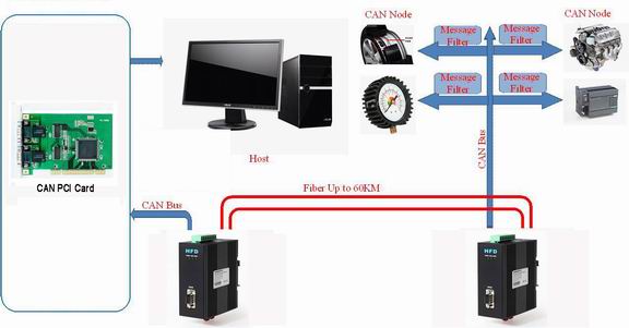
New No-cascading CAN Bus Fiber Optic Converter into Turkey Market
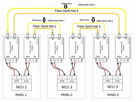
The Bueno New No-cascading long distance Canbus fiber Optic converter just signed the contract with Turkey system integrator who is to install the new Canbus fiber optic converter to their fire safety systems. Because the traditional CAN BUS fiber optic converter has the defects problem of cascading,which will stop work working when distance is long or bit rate is high.Bueno new canbus fiber optic converter has successfully solved this problem. In this project the longest distance is 5.5km,the old converters can't reach this distance, so the integrator finally choosed us.
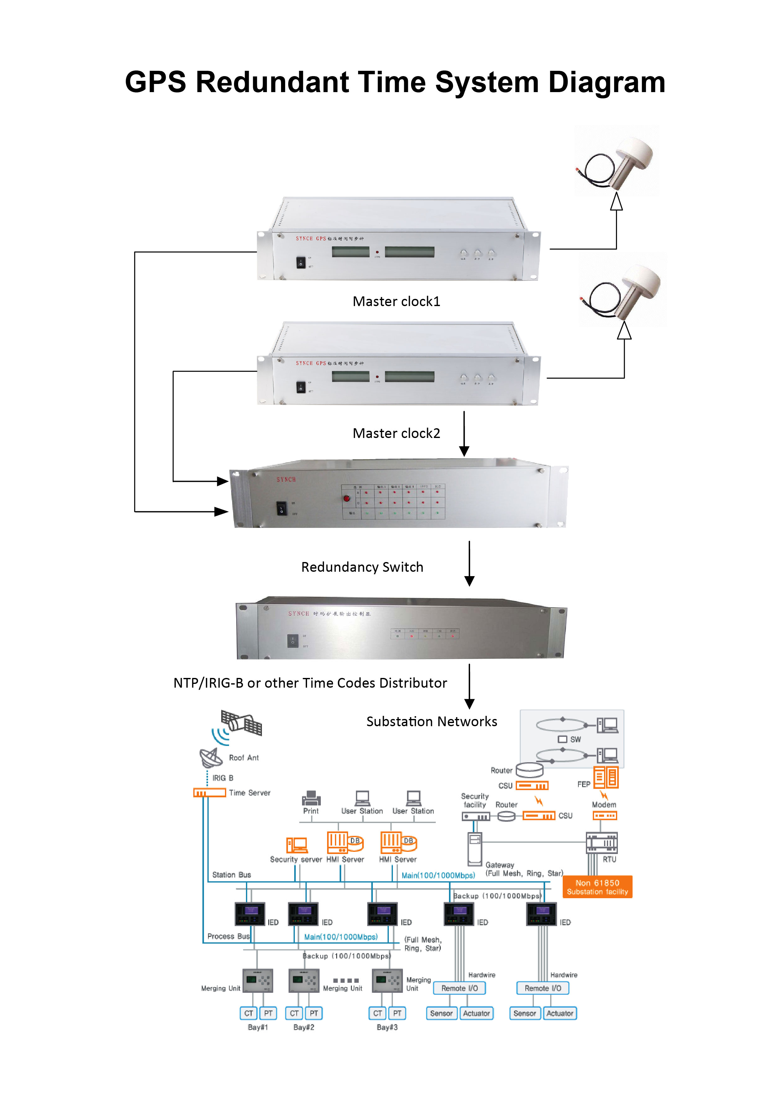
GPS Redundant Time Systems
GPS Redundancy Time System Solution
Overview:
Buenoptic can offer full GPS redundancy time solutions,the system can switch the GPS time source to another one when one master clock is out of GPS signal,thus it's the guarantee of high accuracy time synchrozination.For the important places such as big substations,mobile telecommunication and other sites,the GPS time server must provide 24-hour time synchronization without any disruption.The traditional single GPS source master clock might lose signal or stop work due to antenna fault,power supply loss or master clock defection,which might cause the time output out of synchronization.With Buenoptic SYNCH(SY) series GPS redundancy time system, the time server system's safety and accuracy will be greatly improved.
Structure of SY GPS redundancy time system:
GPS antennas: 2 pieces. 30 meter long cable each,with surge-protection(SPD).
Master clock: 2 pieces, with serial time outputs to time switch.
Time switch: 1 piece.
Time code distributor: 1 piece or more. 1 distributor can support 1 to 24 channels of NTP/SNTP,IRIG-B,RS232,fiber optic time output ports.
Time switch lantency: 0
2 Channel CAN BUS Fiber Optic Converter(No Cascading)
HFD-FO-CAN DIN Rail 2 Channel CAN Fiber optic Converter
Transmission rate:
The HFD-FO-CAN support all the transmission speeds (transmission rates):0-1Mbps.The converter can support 2 channels of CAN data input.The transmission rate is set automatically as soon as the canbus HFD-FO-CAN receives a frame. The setting or adjustment is dependent on the transmission rate. Depending on the HFD-FO-CAN Settings in automatical mode,
Segment monitoring at the optical line:
Each receiver monitors the optical line port connected to it for recive framesand status. If faulty frames are received by the receiver, or no single for longer than the maximum permitted time, forwarding of the received signals is blocked until the port status is ok,frames can be received again correctly.
Network Topologies:
The following network topologies can be realized with the HFD-FO-CAN:
- Point-to-point topologies
- Multi-drop Bus
Fiber Mode: Single mode or Multi Mode
Product Feature:
Buffer function:The HFD-FO-CAN can protect the data from being lost. Anti-stream: 1000 frames.
No cascading: The HFD-FO-CAN has no cascading,no frame loss when data is at high rate or long distance transmission.
Reliablity: Compared with other brands,the HFD-FO-CAN can help build up more stable and secure networks.
Dual 2 Channels of CAN BUS input: The converter can be connected to 2 CAN BUS devices simultaneously
|
Technical Data |
|
|
Voltage/power supply |
12-36V DC |
|
Operating voltage |
9 V to 30 V DC, typ. 24 V, |
|
Current consumption |
typ. 80 mA@24V |
|
Output voltage/current (Pin 6 Sub-D socket) |
5 V +5%,–10%/ 90 mA |
|
Signaling contact Signal transmission |
Max .switch DC24V@2A or This email address is being protected from spambots. You need JavaScript enabled to view it. |
|
Transmission rate |
0-1Mbps |
|
Setting transmission rate |
Automatic or Switch setting |
|
Bit error rate |
< 10-9 |
|
Electrical port |
2 ways of Terminal or DB9 |
|
Input/output signal |
CAN2.0A, CAN2.0B,ISO-11898 |
|
PIN assignment |
|
|
Optical ports |
1 or 2 (2 as standard) |
|
Wavelength |
SM:1310, MM:850nm |
|
optical power:– in glass fiber 9/125um – in glass fiber G 62.5/125 |
-9dBm – -18 dBm -13 dBm – -20 dBm |
|
Receiver sensitivity |
-34dBm |
|
Transmission distance:with glass fiber 9/125um with glass fiber G 62,5/125 |
0 – 20,000 m (0.3 dB/km) 0 – 3,000 m (2.0 dB/km) |
|
Connector |
ST/FC/SC |
|
Others |
|
|
Ambient temperature |
-30 °C to +70 °C |
|
Storage temperature |
–40 °C to +85 °C |
|
Relative humidity |
<95 %, non-condensing |
|
Protection class |
IP 30 |
|
Dimensions (W x H x D) |
43(W) x 88.5(D) x125.5(H)mm |
|
Housing material/Color |
Die-cast zinc/Black |
|
Weight |
approx. 600 g |
Electromagnetic compatibility (EMC)
Limit class B (EN 55022)
EN 61000-4-2
EN 61000-4-3)
Burst: On power supply lines and shielded RS 485 bus lines: ±2 kV (EN 61000-4-4)
Surge: Power lines: ±1 kV symmetrical,Shielded RS 485 lines: ±2 kV asymmetrical (EN 61000-4-5)
Application: The HFD-FO-CAN converter can be used in fire alarm system,radar system,security,industrial automation,solar palnt and other industrial fields.
Ordering Information:
|
Model Number |
Description |
Fiber No. |
Fiber Mode |
Fiber Connector |
|
HFD-FO-CAN2-P1M |
Point to point Link,Single Fiber(BI-DI), 2km |
1 |
Multi Mode |
ST/SC/FC |
|
HFD-FO-CAN2-P2M |
Point to point Link,Dual Fiber, 2km |
2 |
Multi Mode |
ST/SC/FC |
|
HFD-FO-CAN2-P1S |
Point to point Link,Single Fiber(BI-DI), 20km |
1 |
Single Mode |
ST/SC/FC |
|
HFD-FO-CAN2-P2S |
Point to point Link,Dual Fiber, 20km |
2 |
Single Mode |
ST/SC/FC |
10/100/1000M(Gigabit) Industrial Media Converter
Gigabit Industrial Media Converter
Model Number: HFD-FO-1000M
|
OPTICAL |
|
|
Number of Fibers |
2 or 1 |
|
Wavelength |
SM:1310/1550nm, MM:850/1310nm |
|
Fiber Type |
9/125μ m(SM) |
|
Distance |
0 ~ 25km, 0~40km, 0~60km, 0-80km |
|
Connector Type |
ST/FC/SC |
|
GENERAL |
|
|
Operating Temperature |
-40 ~ 70C / -40 ~ +158F |
|
Relative Humidity |
0 ~ 95% non-condensing |
|
Mean Time Between Failure (MTBF) |
> 600, 000hrs |
|
Power Supply Adaptors |
AC 220V 110v or DC+110V, +5V, +12V, +24V, +48V Option |
|
Enclosure Color |
Blue or Black |
|
Dimensions ( H× W× D ) |
120× 40× 92mm DIN Rail |
Ordering Information:
|
Model Number |
Description |
Fiber No. |
Fiber Mode |
Fiber Connector |
|
HFD-FO-1000M-P1M |
Point to point Link,Single Fiber(BI-DI), 2km |
1 |
Multi Mode |
ST/SC/FC |
|
HFD-FO-1000M-P2M |
Point to point Link,Dual Fiber, 2km |
2 |
Multi Mode |
ST/SC/FC |
|
HFD-FO-1000M-P1S |
Point to point Link,Single Fiber(BI-DI), 20km |
1 |
Single Mode |
ST/SC/FC |
|
HFD-FO-1000M-P2S |
Point to point Link,Dual Fiber, 20km |
2 |
Single Mode |
ST/SC/FC |
10/100M Industrial Media Converter

10/100M Industrial Media Converter
Model Number: HFD-FO-100M
The HFD Series Industrial Fiber media converter is fully assembled using SMT components for stability and reliability.
|
ETHERNET |
|
|
Supporting standards |
IEEE802.3 10Base-T, 100Base-T |
|
Data Rate |
10/100Mbps auto-sensing, Full Duplex or Half Duplex |
|
Physical Interface |
RJ45, DCE interface |
|
OPTICAL |
|
|
Number of Fibers |
2 or 1 |
|
Wavelength |
SM:1310/1550nm, MM:850/1310nm |
|
Fiber Type |
9/125μ m(SM) |
|
Distance |
0 ~ 25km, 0~40km, 0~60km, 0-80km |
|
Connector Type |
ST/FC/SC |
|
GENERAL |
|
|
Operating Temperature |
-40 ~ 70C / -40 ~ +158F |
|
Relative Humidity |
0 ~ 95% non-condensing |
|
Mean Time Between Failure (MTBF) |
> 600, 000hrs |
|
Power Supply Adaptors |
AC 220V 110v or DC+110V, +5V, +12V, +24V, +48V Option |
|
Enclosure Color |
Blue or Black |
|
Dimensions ( H× W× D ) |
DIN Rail 120*30*88mm |
Ordering Information
|
Model Number |
Description |
Fiber No. |
Fiber Mode |
Fiber Connector |
|
HFD-FO-100M-P1M |
Point to point Link,Single Fiber(BI-DI), 2km |
1 |
Multi Mode |
ST/SC/FC |
|
HFD-FO-100M-P2M |
Point to point Link,Dual Fiber, 2km |
2 |
Multi Mode |
ST/SC/FC |
|
HFD-FO-100M-P1S |
Point to point Link,Single Fiber(BI-DI), 20km |
1 |
Single Mode |
ST/SC/FC |
|
HFD-FO-100M-P2S |
Point to point Link,Dual Fiber, 20km |
2 |
Single Mode |
ST/SC/FC |
Telephone Over Fiber Optic Multiplexer(Converter)
Telephone/Ethernet Fiber Optic Multiplexer
Buenoptic Fiber Optic Transmission Systems support 1~4 Channel telephone + 1 Channel Ethernet, over one multi-mode or single-mode optical fiber. These fiber optic transmitter and fiber optic receiver are available for stand-alone or rack-mount installations. FC, ST or SC optical connectors is optional.
Plug and Play design ensures adjustment-free installation and operation, and optical adjustments are never required. LED indicators are provided to instantly monitor the system operating status.
Buenoptic Fiber Optic Transmission Systems can transmit video, audio, data, telephone, alarm and ethernet signals,Our Fiber Optic Integrated Platform is A System Designed By You - For You. No matter how complex your system is, you just give your request to us, We will give you a satisfactory solution and design diagram.
Specifications
Telephone:
|
Connector |
Standard RJ11 |
|
Phonetic bandwidth |
8KHz |
|
Work mode |
Point to point hot line, program controlling switch/extension mode |
|
Distortion |
<1% |
Ethernet:
|
Work mode |
Full duplex/half duplex |
|
Data Rate |
10/100Mbps(AUTO) |
|
connection terminal |
RJ45 |
|
Electrical & Mechanical |
|
|
Input Power Requirements: |
DC 5V@2A |
|
Power Adapter: |
AC 90V~240V |
|
Power Consumption: |
< 3W |
|
Stand-Alone Dimensions: |
183mm × 154mm × 30mm |
|
Shipping Weight: |
(include Transmitter & Receiver ) 1.5kg |
|
Environmental |
|
|
Operating Temperature: |
-20°C ~ +75°C |
|
Storage Temperature: |
-40°C ~ +85°C |
|
Relative Humidity: |
0% ~ 95% (non-condensing) |
|
MTBF: |
>100,000 hours |
Ordering Information & Optical Specifications
|
Model |
Fiber Mode |
Connecter |
Telephone Channel |
Optical Power Budget |
Max Transmission Distance |
|
Transmitter & Receiver |
|||||
|
HFB-FO-TEL-1CH |
SM |
FC/ST/SC |
1 |
18dB |
25km |
|
HFB-FO-TEL-2CH |
SM |
FC/ST/SC |
2 |
18dB |
25km |
|
HFB-FO-TEL-4CH |
SM |
FC/ST/SC |
4 |
18dB |
25km |
Note:
• The Optical Power Budget data fit Mulit-mode(62.5/125 μm),Single-Mode(9/125 μm).
• When using 50/125 μm multimode fiber, subtract 3 dB from the optical power budget.
• Optical transmission distance is limited to optical loss of the fiber and any additional loss introduced by connectors, splices and patch panels.
• Maximum transmission distance is also limited by fiber bandwidth.
• Power adapter is manufactured by third party and is supplied with fitted screw-terminal output cables.Power adapter included (for standalone) US, European, UK or Australian power plug.
• Please feel free to consult factory for any special requirement and customization.
• Due to continuous improvement, all fiber optic transmission systems and video over fiber product specifications are subject to change without further notice.