Sidebar
News Press

Administrator
FC Single Mode Patch Cord
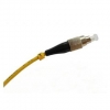
FC fiber optic patch cord features low cost, simplicity as well as good durability, the ceramic ferrules make them accurate alignment. FC fiber optic patch cord are with a locking tab on the cable termination, they are push and pull type fiber optic connectors. Generally FC fiber optic patch cord life cycle is about one thousand times mating cycle.
FC fiber patch cord available for PC/UPC/APC version, provide both SM and MM, 0.9mm, 2.0mm, 3.0mm cable diameter for choose, different fiber length by customers’ request.
Description
Cable Color: Yellow
Fiber counts: 1 Fiber (Simplex)
Fiber type: Singlemode (9/125um)
Connector type: FC
Connector counts: 2 connectors
Application
¨ Telecommunication
¨ CATV, FTTH, LAN
¨ Fiber oiptic sensors
¨ Optical transmission system
¨ Test equipment
Features
¨ Screw-thread coupling mechanism
¨ Ceramic ferrules connectors
¨ Low insertion loss, high return loss
¨ Excellent mechanical endurance
¨ High credibility and stability
¨ Good in repeatability and exchangeability
¨ 100% Insertion, Return Loss, End Face and Interference inspection
Technical Data
|
Parameter |
Unit |
FC, SC, LC |
ST, MU |
MTRJ, MPO |
E2000 |
||||||||
|
SM |
MM |
SM |
MM |
SM |
MM |
SM |
|||||||
|
PC |
UPC |
APC |
PC |
PC |
UPC |
PC |
PC |
UPC |
PC |
PC |
APC |
||
|
Insertion Loss |
dB |
≤0.3 |
≤0.2 |
≤0.3 |
≤0.2 |
≤0.3 |
≤0.2 |
≤0.2 |
≤0.3 |
≤0.2 |
≤0.2 |
≤0.3 |
≤0.3 |
|
Return Loss |
dB |
≥45 |
≥50 |
≥60 |
≥30 |
≥45 |
≥50 |
≥30 |
≥45 |
≥50 |
≥35 |
≥55 |
≥75 |
|
Repeatability |
dB |
≤0.1 |
|||||||||||
|
Durability |
dB |
≤0.2dB typical change, 1000 matings |
|||||||||||
|
Operating temperature |
℃ |
-20 ~ +75 |
|||||||||||
|
Storage temperature |
℃ |
-40 ~ +85 |
|||||||||||
Ordering Informaion
|
Connector |
Fiber Core |
Cable Diameter |
Fiber Type |
Polishing |
Cable Jacket |
Cable Color |
Fiber Length |
|
LC SC FC ST D4 MU DIN SMA MPO MTRJ E2000 … |
Simplex Duplex |
0.9mm 2.0mm 3.0mm |
SM:9/125um MM:50/125um MM:62.5/125um OM3 |
PC UPC APC |
PVC LSZH |
Yellow Orange Aqua others |
1M 2M 3M … 10M 20M 30M … |
SC Multi Mode Patch Cord
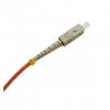
SC fiber optic patch cord features low cost, simplicity as well as good durability, the ceramic ferrules of SC fiber optic patch cord make them accurate alignment. SC patch cord with a locking tab on the cable termination, they are push and pull type fiber optic connectors. Generally SC fiber optic patch cords life cycle is about one thousand times mating cycle.
SC fiber patch cord available for PC/UPC/APC version, provide both SM, MM, simplex and duplex, 0.9mm, 2.0mm, 3.0mm cable diameter for choose, different fiber length by customers request.
Description
Cable Color: Orange
Fiber counts: 1 Fiber (Simplex)
Fiber type: Multimode (50/125um or 62.5/125um)
Connector type: SC
Connector counts: 2 connectors
Application
¨ Telecommunication
¨ CATV, FTTH, LAN
¨ Fiber oiptic sensors
¨ Optical transmission system
¨ Test equipment
Features
¨ Push-pull, key-oriented coupling mechanism
¨ Ceramic ferrules connectors
¨ Low insertion loss, high return loss
¨ Excellent mechanical endurance
¨ High credibility and stability
¨ Good in repeatability and exchangeability
¨ 100% Insertion, Return Loss, End Face and Interference inspection
Technical Data
|
Parameter |
Unit |
FC, SC, LC |
ST, MU |
MTRJ, MPO |
E2000 |
||||||||
|
SM |
MM |
SM |
MM |
SM |
MM |
SM |
|||||||
|
PC |
UPC |
APC |
PC |
PC |
UPC |
PC |
PC |
UPC |
PC |
PC |
APC |
||
|
Insertion Loss |
dB |
≤0.3 |
≤0.2 |
≤0.3 |
≤0.2 |
≤0.3 |
≤0.2 |
≤0.2 |
≤0.3 |
≤0.2 |
≤0.2 |
≤0.3 |
≤0.3 |
|
Return Loss |
dB |
≥45 |
≥50 |
≥60 |
≥30 |
≥45 |
≥50 |
≥30 |
≥45 |
≥50 |
≥35 |
≥55 |
≥75 |
|
Repeatability |
dB |
≤0.1 |
|||||||||||
|
Durability |
dB |
≤0.2dB typical change, 1000 matings |
|||||||||||
|
Operating temperature |
℃ |
-20 ~ +75 |
|||||||||||
|
Storage temperature |
℃ |
-40 ~ +85 |
|||||||||||
Ordering Informaion
|
Connector |
Fiber Core |
Cable Diameter |
Fiber Type |
Polishing |
Cable Jacket |
Cable Color |
Fiber Length |
|
LC SC FC ST D4 MU DIN SMA MPO MTRJ E2000 … |
Simplex Duplex |
0.9mm 2.0mm 3.0mm |
SM:9/125um MM:50/125um MM:62.5/125um OM3 |
PC UPC APC |
PVC LSZH |
Yellow Orange Aqua others |
1M 2M 3M … 10M 20M 30M … |
SC Single Mode Patch Cord
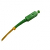
SC fiber optic patch cord features low cost, simplicity as well as good durability, the ceramic ferrules of SC fiber optic patch cord make them accurate alignment. SC patch cord with a locking tab on the cable termination, they are push and pull type fiber optic connectors. Generally SC fiber optic patch cords life cycle is about one thousand times mating cycle.
SC fiber patch cord available for PC/UPC/APC version, provide both SM, MM, simplex and duplex, 0.9mm, 2.0mm, 3.0mm cable diameter for choose, different fiber length by customers request.
Description
Cable Color: Orange
Fiber counts: 1 Fiber (Simplex)
Fiber type: Multimode (50/125um or 62.5/125um)
Connector type: SC
Connector counts: 2 connectors
Application
¨ Telecommunication
¨ CATV, FTTH, LAN
¨ Fiber oiptic sensors
¨ Optical transmission system
¨ Test equipment
Features
¨ Push-pull, key-oriented coupling mechanism
¨ Ceramic ferrules connectors
¨ Low insertion loss, high return loss
¨ Excellent mechanical endurance
¨ High credibility and stability
¨ Good in repeatability and exchangeability
¨ 100% Insertion, Return Loss, End Face and Interference inspection
Technical Data
|
Parameter |
Unit |
FC, SC, LC |
ST, MU |
MTRJ, MPO |
E2000 |
||||||||
|
SM |
MM |
SM |
MM |
SM |
MM |
SM |
|||||||
|
PC |
UPC |
APC |
PC |
PC |
UPC |
PC |
PC |
UPC |
PC |
PC |
APC |
||
|
Insertion Loss |
dB |
≤0.3 |
≤0.2 |
≤0.3 |
≤0.2 |
≤0.3 |
≤0.2 |
≤0.2 |
≤0.3 |
≤0.2 |
≤0.2 |
≤0.3 |
≤0.3 |
|
Return Loss |
dB |
≥45 |
≥50 |
≥60 |
≥30 |
≥45 |
≥50 |
≥30 |
≥45 |
≥50 |
≥35 |
≥55 |
≥75 |
|
Repeatability |
dB |
≤0.1 |
|||||||||||
|
Durability |
dB |
≤0.2dB typical change, 1000 matings |
|||||||||||
|
Operating temperature |
℃ |
-20 ~ +75 |
|||||||||||
|
Storage temperature |
℃ |
-40 ~ +85 |
|||||||||||
Ordering Informaion
|
Connector |
Fiber Core |
Cable Diameter |
Fiber Type |
Polishing |
Cable Jacket |
Cable Color |
Fiber Length |
|
LC SC FC ST D4 MU DIN SMA MPO MTRJ E2000 … |
Simplex Duplex |
0.9mm 2.0mm 3.0mm |
SM:9/125um MM:50/125um MM:62.5/125um OM3 |
PC UPC APC |
PVC LSZH |
Yellow Orange Aqua others |
1M 2M 3M … 10M 20M 30M … |
ST Multi Mode Patch Cord

ST fiber patch cord features low cost, simplicity as well as good durability, the ceramic ferrules make accurate alignment. ST fiber optic patch cords are with a locking tab on the cable termination, they are push and pull type fiber optic connectors.
ST fiber patch cord available for both SM and MM, provide simplex and duplex, 0.9mm, 2.0mm, 3.0mm cable diameter for choose, different fiber length by customers’ request.
Description
Cable Color: Orange
Fiber counts: 1 Fiber (Simplex)
Fiber type: Multimode (50/125um or 62.5/125um)
Connector type: ST
Connector counts: 2 connectors
Application
¨ Telecommunication
¨ CATV, FTTH, LAN
¨ Fiber oiptic sensors
¨ Optical transmission system
¨ Test equipment
Features
¨ Twist-lock bayonet coupling mechanism
¨ Ceramic ferrules connectors
¨ Low insertion loss, high return loss
¨ Excellent mechanical endurance
¨ High credibility and stability
¨ Good in repeatability and exchangeability
¨ 100% Insertion, Return Loss, End Face and Interference inspection
Technical Data
|
Parameter |
Unit |
FC, SC, LC |
ST, MU |
MTRJ, MPO |
E2000 |
||||||||
|
SM |
MM |
SM |
MM |
SM |
MM |
SM |
|||||||
|
PC |
UPC |
APC |
PC |
PC |
UPC |
PC |
PC |
UPC |
PC |
PC |
APC |
||
|
Insertion Loss |
dB |
≤0.3 |
≤0.2 |
≤0.3 |
≤0.2 |
≤0.3 |
≤0.2 |
≤0.2 |
≤0.3 |
≤0.2 |
≤0.2 |
≤0.3 |
≤0.3 |
|
Return Loss |
dB |
≥45 |
≥50 |
≥60 |
≥30 |
≥45 |
≥50 |
≥30 |
≥45 |
≥50 |
≥35 |
≥55 |
≥75 |
|
Repeatability |
dB |
≤0.1 |
|||||||||||
|
Durability |
dB |
≤0.2dB typical change, 1000 matings |
|||||||||||
|
Operating temperature |
℃ |
-20 ~ +75 |
|||||||||||
|
Storage temperature |
℃ |
-40 ~ +85 |
|||||||||||
Ordering Informaion
|
Connector |
Fiber Core |
Cable Diameter |
Fiber Type |
Polishing |
Cable Jacket |
Cable Color |
Fiber Length |
|
LC SC FC ST D4 MU DIN SMA MPO MTRJ E2000 … |
Simplex Duplex |
0.9mm 2.0mm 3.0mm |
SM:9/125um MM:50/125um MM:62.5/125um OM3 |
PC UPC APC |
PVC LSZH |
Yellow Orange Aqua others |
1M 2M 3M … 10M 20M 30M … |
ST Single Mode Patch Cord
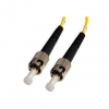
ST fiber patch cord features low cost, simplicity as well as good durability, the ceramic ferrules make accurate alignment. ST fiber optic patch cords are with a locking tab on the cable termination, they are push and pull type fiber optic connectors.
ST fiber patch cord available for both SM and MM, provide simplex and duplex, 0.9mm, 2.0mm, 3.0mm cable diameter for choose, different fiber length by customers’ request.
Description
Cable Color: Yellow
Fiber counts: 1 Fiber (Simplex)
Fiber type: Singlemode (9/125um)
Connector type: ST
Connector counts: 2 connectors
Application
¨ Telecommunication
¨ CATV, FTTH, LAN
¨ Fiber oiptic sensors
¨ Optical transmission system
¨ Test equipment
Features
¨ Twist-lock bayonet coupling mechanism
¨ Ceramic ferrules connectors
¨ Low insertion loss, high return loss
¨ Excellent mechanical endurance
¨ High credibility and stability
¨ Good in repeatability and exchangeability
¨ 100% Insertion, Return Loss, End Face and Interference inspection
Technical Data
|
Parameter |
Unit |
FC, SC, LC |
ST, MU |
MTRJ, MPO |
E2000 |
||||||||
|
SM |
MM |
SM |
MM |
SM |
MM |
SM |
|||||||
|
PC |
UPC |
APC |
PC |
PC |
UPC |
PC |
PC |
UPC |
PC |
PC |
APC |
||
|
Insertion Loss |
dB |
≤0.3 |
≤0.2 |
≤0.3 |
≤0.2 |
≤0.3 |
≤0.2 |
≤0.2 |
≤0.3 |
≤0.2 |
≤0.2 |
≤0.3 |
≤0.3 |
|
Return Loss |
dB |
≥45 |
≥50 |
≥60 |
≥30 |
≥45 |
≥50 |
≥30 |
≥45 |
≥50 |
≥35 |
≥55 |
≥75 |
|
Repeatability |
dB |
≤0.1 |
|||||||||||
|
Durability |
dB |
≤0.2dB typical change, 1000 matings |
|||||||||||
|
Operating temperature |
℃ |
-20 ~ +75 |
|||||||||||
|
Storage temperature |
℃ |
-40 ~ +85 |
|||||||||||
Ordering Informaion
|
Connector |
Fiber Core |
Cable Diameter |
Fiber Type |
Polishing |
Cable Jacket |
Cable Color |
Fiber Length |
|
LC SC FC ST D4 MU DIN SMA MPO MTRJ E2000 … |
Simplex Duplex |
0.9mm 2.0mm 3.0mm |
SM:9/125um MM:50/125um MM:62.5/125um OM3 |
PC UPC APC |
PVC LSZH |
Yellow Orange Aqua others |
1M 2M 3M … 10M 20M 30M ... |
HFD RS485 Fiber Converters on Wuxi Subway Project
On 26th,May 2013,Bueno sent engineer team to Wuxi subway project to help the projectors construct the wiring of data communication which is an important part of subway signal control.
Wuxi subway project with 8 subway lines will come to conclusion in 2013,the subway signal control project had already been started from 2012,which has used 910 pieces of HFD series DIN Rail RS-485 fiber optic converters made by Bueno.The HFD fiber optic converters are placed in Siemen's cabinet devices and the 2 cabinets distance are just 20 to 50 meters,due to the high magnetic inference in the subway tubes, the projector has to use fiber optic cables to connect these devices to avoid the magnetic interference,thus the HFD series are finally choosed by the projector.


VGA, DVI, HDMI, Definition
There are once again many terms in this sermon so grab the post for this episode so you can get more detail.
VGA
Introduced in 1987, the Video Graphics Array connector (or VGA) is the standard blue 15-pin connector we have all dealt with. It has also been called RGB, D-sub or “that blue cable”. The VGA cable supports resolutions from 640×400 to 2048×1536. With the right equipment, you might be able to pinch a little more res out but that is infrequent. A VGA connection is ANALOG and cable lengths are good up to 25-30 ft.
You may have heard terms like VGA, SVGA, SXGA, HDTV and WUXGA but these all just define the vector (resolution) of the signal. For PCs, we do not typically use this rating but this comes in to play when looking at projectors given that there native resolution is frequently considered important.
VGA is to be phased out by 2013 but I am sure support will be around for years after.
DVI
Introduced in 1999, the Digital Visual Interface (or DVI) is the 29-pin connector that came after VGA. It has been called DVI-DVI-D, the “white one” connector or I. This connector is digital, which means that data is transmitted and is not affected by noise or distortion. Something else to consider is that when your display is on its native resolution the DVI the source is based on each pixel on the monitor. When you use a VGA connector, the pixels are not individually lit and the lit pixels are affected by other pixels. For those of you with two monitors, one on VGA and one on DVI, you will notice the DVI looks slight more crisp. This signal is reason behind that. If you have a card that has VGA, DVI and HDMI try to not to use the VGA and get an adapter for the HDMI. You will get better results.
Now as far as the resolutions for DVI you need to understand single and dual DVI links. Look at your DVI connector and if there are missing pins in the middle then it is a single link DVI cable.
Just as an FYI, the DVI connector includes pins for analog signal, which is how you can use one of those adapters to go to VGA.
The highest resolution for a single DVI link is 2098×1311 so when a higher resolution is need the dual DVI link kicks in and you can get that higher resolution. Your video card must support dual link of course and single link is most common.
There is also Display Data Channel (or DDC or DDC2) on pins six and seven that have information that tells your PC the type of monitor it is. Modern VGA cables also have DDC/DDC2. This ID data is how your PC knows the type and resolution and what drivers to get for your monitors. As a recap, six pins are for data, six pins for analog signal, six pins for data two, five pins for monitor data and six for shield.
Cable lengths are good to 15 ft at 1080 while you can go longer with lower resolutions or by using a booster.
DVI is a great connector but since it does not include audio, it is losing out to HDMI.
BELOW DATA COPIED FROM WIKI at http://en.wikipedia.org/wiki/Digital_Visual_Interface
- Example display modes (single link):
- HDTV (1,920 × 1,080) @ 60 Hz with CVT-RB blanking (139 MHz)
- UXGA (1,600 × 1,200) @ 60 Hz with GTF blanking (161 MHz)
- WUXGA (1,920 × 1,200) @ 60 Hz with CVT-RB blanking (154 MHz)
- SXGA (1,280 × 1,024) @ 85 Hz with GTF blanking (159 MHz)
- WXGA+ (1440 × 900) @ 60 Hz (107 MHz)
- WQUXGA (3,840 × 2,400) @ 17 Hz (164 MHz)
- Example display modes (dual link):
- QXGA (2,048 × 1,536) @ 75 Hz with GTF blanking (2 × 170 MHz)
- HDTV (1,920 × 1,080) @ 85 Hz with GTF blanking (2 × 126 MHz)
- WUXGA (1,920 × 1,200) @ 120 Hz with CVT-RB blanking (2 x 154 MHz)
- WQXGA (2,560 × 1,600) @ 60 Hz with GTF blanking (2 × 174 MHz) (30-inch / 762 mm Apple, Dell, Gateway, HP, NEC, Quinux, and Samsung LCDs)
- WQXGA (2,560 × 1,600) @ 60 Hz with CVT-RB blanking (2 × 135 MHz) (30-inch / 762 mm Apple, Dell, Gateway, HP, NEC, Quinux, and Samsung LCDs)
- WQUXGA (3,840 × 2,400) @ 33 Hz with GTF blanking (2 × 159 MHz)
HDMI
Introduced in 2003, High-Definition Multimedia Interface (HDMI) is the 19-pin digital connector standard most people tend to favor now. This connector and cable supports any uncompressed video format and carries eight channels of audio. It also can carry Ethernet and a CEC connection which is how your Samsung TV can remote control your Samsung Blu-ray through the HDMI cable. Magic eh? Other names are Aquos Link, Viera Link, Easylink and Bravia Sync.
Most of us have the Type A Category 1 connector that we use for our home theater equipment.
HDMI cables made currently under the 1.3 and 1.4 spec fall under Category 1, which is Standard Speed and Category 2 which is High-Speed. Category 1 cable is fine for most uses but if you are going 3D, cinema 4K, 2160 or 1080p then you want the Category 2.
Cable length is generally limited to 16 feet (Category 1) but with a higher quality cable (Category 2) you can go to almost 50 feet.
Also there were specs released with versions 1.2, 1.3 and 1.4 the cables are only different in bit rate. With version 1.4, 3D support was added. It gets hard to weed through the advertised specs (which they are not supposed to advertise anyway) so just get cables that are 1.3 or 1.4 when you buy.
HDMI also uses the same signal as DVI so no signal conversion is necessary. You just need a simple DVI-HDMI adapter but you lose the audio. This works well, however not all device support HDCP so you may have issues. Check with your manuals for further information on your source device.
Industrial Ethernet Switch Market Seeing New Growth Areas
Originally largely reliant on discrete automation applications, growth in the market for industrial Ethernet switches is increasingly driven by use in infrastructure installations and process automation.
These new opportunities, coupled with Ethernet's continued cementing of its position as the industrial network infrastructure of choice, including for the coming Internet of Things, are fueling double-digit growth in this important segment, according to ARC Advisory Group in its most recent update on the industrial Ethernet switch market.
Infrastructure applications ranging from smart grid implementations, in particular electrical substation automation, to intelligent rail, highway, and other transportation projects are increasingly reliant on industrial Ethernet. Continued reliance on the infrastructure markets for growth is evident in one of the largest growth markets, China, where electric power generation, power T&D, and transportation are the leading consumers of IE switches.
In process automation, industrial Ethernet is already the backbone network of choice at the control level and is now migrating to the device level. “Industrial Ethernet switch suppliers are faced with a widening landscape upon which to direct their strategies. Device characteristics, standards support, toolsets supplied, and a myriad of other decisions must be driven by which market subsets are targeted,” according to vice president Chantal Polsonetti, the principal author of ARC's “Industrial Ethernet Switches Global Market Research Study”.
Industrial Ethernet is increasingly establishing itself as the common industrial network, displacing application-specific fieldbuses across a broad spectrum of industries, says ARC. At the same time, these devices continue to adopt new standards from their COTS-based cousins in areas ranging from IEEE 1588 clock synchronization to IEEE 802.1x-based security to IEC 62439-3-based redundancy. These attributes make industrial Ethernet the increasingly popular network infrastructure of choice for the coming Internet of Things and Industrial Internet.
The expanded potential market and its varying functional and standards requirements results in a continued variety of switch configurations beyond the typical 5 to 8 port DIN Rail Fast Ethernet device. Increasing sophistication of industrial Ethernet offerings is evident in the number of configuration options available, including routing switches. Growth in the new category of “Lightly Managed” switches reflects the move to provide increased ease of use and configuration, particularly for the industrial or non-IT oriented customer.
Concurrent with the market growth, the industrial Ethernet switch market has experienced a wave of acquisitions. While some were made as an entry to new markets, such as electrical substation automation, a number were made by suppliers of peripheral products (connectors, HMI, panel meters) looking to take advantage of surging interest in industrial Ethernet infrastructure in hope of pulling in their complementary product lines.
Modbus Plus(MB+) Fiber Media Converters
Description:
Transmission rate
The HFD-FO-MBP Series Modbus fiber optic converters support all the transmission speeds between 0 ~ 1MB.The transmission rate is set automatically as soon as the HFD receives a frame. The HFD system is a high transparent low-latency transmission system, this system in many aspects has excellent performance.The fiber-optic repeater HFD supports the any rate.
Signal regeneration
The modules regenerate the signal form and amplitude of the data received. This allows up to 200 HFD Modbus Plus converter to be cascaded.
Segment monitoring at the RS 485 port
Each receiver monitors the RS 485 bus segment connected to it for faulty frames or continuously busy networks. If faulty frames are received by the receiver, or if the network is busy for longer than the maximum permitted send time, forwarding of the received signals is blocked until frames can be received again correctly.
Segment monitoring at the optical line
Each receiver monitors the optical line port connected to it for recive framesand status. If faulty frames are received by the receiver, or no single for longer than the maximum permitted time, forwarding of the received signals is blocked until the port status is ok,frames can be received again correctly.
Network Topologies
The following network topologies can be realized with the HFD Modbus plus(MB+) optical converter:
_ Point-to-point topology
_ Multi-drop BUS topology
_ Star topology
_ Redundant ring(DSHR)
Combinations of these basic types are also possible. Lines with two optical fibers are used to create the fiber links for these network topologies.If a malfunction – e.g. a break in a fiber line – makes a high degree of field bus network fail-safety necessary, the availability of the network can be increased using a redundant network configuration.
Line topology
In a line structure, the individual RS485 HFDs are connected together by dual-fiber optical fibers. Modules with one optical port are sufficient at the beginning and end of a line, between which modules with two optical ports are necessary.
If single point-to-point connections are to be built up, this can be achieved using two modules each with one optical port.
Star topology
Several modules are combined to form an active RS485 star coupler. Other modules are connected to this by dual-fiber optical fiber lines. The modules of the star coupler are connected to
one another via the electrical port(electrical star segment).All HFD types for different fiber types can be combined using the electrical star segment.
Modules with one or two optical ports can be used to create an active RS485 star coupler. Modules with one optical port are sufficient for connecting a terminal or an RS 485 bus segment to the active star coupler.
Redundant optical ring
This network topology represents a special form of line topology. A high degree of network operating safety is achieved by ”closing“ the optical line. A redundant optical ring can only be realized with modules with two optical ports of the same type.
An interruption of one or both optical fibers between two modules is detected by the HFD and the ring is transformed into an optical line.If one module fails only those terminals connected to this module or the RS 485 segment are uncoupled from the ring. The remainder of the network itself continues to function as a line. The error is indicated by the LEDs on the two HFD connected to the malfunctioning optical fiber and their signaling contacts. The segmentation is lifted automatically as soon as both modules recognize that the segmented field bus network is functioning correctly with the test frames.
| Voltage/power supply | 5V/12V/24 DC |
| Operating voltage | 12 V to 30 V DC, typ. 24 V, |
| Current consumption | typ. 120 mA@24V |
| Signaling contact | Max .switch DC24V@2A or This email address is being protected from spambots. You need JavaScript enabled to view it. This e-mail address is being protected from spambots. You need JavaScript enabled to view it |
| Signal transmission | |
| Transmission rate | 1MB |
| Setting transmission rate | Automatic |
| Bit error rate | < 10-9 |
| Transmission principle | Transparent transmission |
| Delay time (Electrical port) | ≤2us/Port |
| Delay(Opticale Fiber Port) | ≤1.6us/Station |
| Retimer (Electrical port) | |
| Input | High speed sampling transmission |
| Single type | NO protocol type |
| Output | Signal distortion < 10ns |
| Edge jitter is less than15ns | |
| Electrical port | |
| Input/output signal | RS 485 level |
| PIN assignment | 5-PIN terminal block |
| Bus properties(All Segments and Fibles) | |
| The equivalent bus | Yes |
| support for single master system | Yes |
| supports multiple master system | Yes |
| The master station Position | Can be placed on any node |
| Optical ports | |
| Wavelength | SM: 1310/1550 nm, MM: 850/1310 nm |
| optical power | |
| – in glass fiber 9/125um | -9dBm – -18 dBm |
| – in glass fiber G 62.5/125 | -13 dBm – -20 dBm |
| Receiver sensitivity | -34dBm |
| Transmission distance | |
| –with glass fiber 9/125um | 0 – 20,000 m (0.3 dB/km) |
| – with glass fiber G 62,5/125 | 0 – 3,000 m (2.0 dB/km) |
| Connector | ST/FC/SC, ST as the standard |
| Electromagnetic compatibility (EMC) | |
| Limit class B (EN 55022) | EN 61000-4-2 EN 61000-4-3 |
| Burst: | |
|
On power supply lines |
±2 kV (EN 61000-4-4) |
| Surge | |
| Power lines,Shielded RS 485 lines |
±1 kV symmetrical,±2 kV asymmetrical (EN 61000-4-5) |
| Others | |
| Ambient temperature | -25 °C to +75 °C |
| Storage temperature | 40 °C to +85 °C |
| Relative humidity | <95 %, non-condensing |
| Protection class | IP 40 |
| Dimensions (H x W x D) | 43(W) x 88.5(D) x 124.5(H) mm |
| Weight | approx. 600 g |
Ordering Information:
|
Model Number |
Description |
Fiber No. |
Fiber Mode |
Fiber Connector |
|
HFD-FO-MBP-P1M |
Point to Point Link,Single Fiber(BI-DI), 2km |
1 |
Multi Mode |
ST/SC/FC |
|
HFD-FO-MBP-P2M |
Point to Point Link,Dual Fiber, 2km |
2 |
Multi Mode |
ST/SC/FC |
|
HFD-FO-MBP-P1S |
Point to Point Link,Single Fiber(BI-DI), 20km |
1 |
Single Mode |
ST/SC/FC |
|
HFD-FO-MBP-P2S |
Point to Point Link,Dual Fiber, 20km |
2 |
Single Mode |
ST/SC/FC |
|
|
|
|
|
|
|
HFD-FO-MBP-M2M |
Multi Point Bus Link,Dual Fiber(BI-DI), 2km |
2 |
Multi Mode |
ST/SC/FC |
|
HFD-FO-MBP-M4M |
Multi Point Bus Link,4 Fiber, 2km |
4 |
Multi Mode |
ST/SC/FC |
|
HFD-FO-MBP-M2S |
Multi Point Bus Link,Dual Fiber(BI-DI), 20km |
2 |
Single Mode |
ST/SC/FC |
|
HFD-FO-MBP-M4S |
Multi Point Bus Link,4 Fiber, 20km |
4 |
Single Mode |
ST/SC/FC |
|
|
|
|
|
|
|
HFD-FO-MBP-R2M |
Redundant Ring Link,Dual Fiber(BI-DI), 2km |
2 |
Multi Mode |
ST/SC/FC |
|
HFD-FO-MBP-R4M |
Redundant Ring Link,4 Fiber, 2km |
4 |
Multi Mode |
ST/SC/FC |
|
HFD-FO-MBP-R2S |
Redundant Ring,Dual Fiber(BI-DI), 20km |
2 |
Single Mode |
ST/SC/FC |
|
HFD-FO-MBP-R4S |
Redundant Ring,4 Fiber, 20km |
4 |
Single Mode |
ST/SC/FC |
Modbus Communication Protocol
Modbus is a serial communications protocol originally published by Modicon (now Schneider Electric) in 1979 for use with its programmable logic controllers (PLCs). Simple and robust, it has since become a de facto standard communication protocol, and it is now a commonly available means of connecting industrial electronic devices. The main reasons for the use of Modbus in the industrial environment are:
- It has been developed with industrial applications in mind
- It is openly published and royalty-free
- It is easy to deploy and maintain
- It moves raw bits or words without placing many restrictions on vendors
Modbus allows for communication between many (approximately 240) devices connected to the same network, for example a system that measures temperature and humidity and communicates the results to a computer. Modbus is often used to connect a supervisory computer with a remote terminal unit (RTU) in supervisory control and data acquisition (SCADA) systems. Many of the data types are named from its use in driving relays: a single-bit physical output is called a coil, and a single-bit physical input is called a discrete input or a contact.
The development and update of Modbus protocols has been managed by the Modbus Organization since April 2004, when Schneider Electric transferred rights to that organization, signaling a clear commitment to openness. The Modbus Organization is an association formed of independent users and suppliers of Modbus compliant devices that seeks to drive the adoption of the Modbus communication protocol suite, and its evolution to address architectures for distributed automation systems across multiple market segments.
Protocol versions
Versions of the Modbus protocol exist for serial port and for Ethernet and other networks that support the Internet protocol suite. There are many variants of Modbus protocols:
- Modbus RTU — This is used in serial communication & makes use of a compact, binary representation of the data for protocol communication. The RTU format follows the commands/data with a cyclic redundancy check checksum as an error check mechanism to ensure the reliability of data. Modbus RTU is the most common implementation available for Modbus. A Modbus RTU message must be transmitted continuously without inter-character hesitations. Modbus messages are framed (separated) by idle (silent) periods.
- Modbus ASCII — This is used in serial communication & makes use of ASCII characters for protocol communication. The ASCII format uses a longitudinal redundancy check checksum. Modbus ASCII messages are framed by leading colon (':') and trailing newline (CR/LF).
- Modbus TCP/IP or Modbus TCP — This is a Modbus variant used for communications over TCP/IP networks, connecting over port 502. It does not require a checksum calculation as lower layers already provide checksum protection.
- Modbus over TCP/IP or Modbus over TCP or Modbus RTU/IP — This is a Modbus variant that differs from Modbus TCP in that a checksum is included in the payload as with Modbus RTU.
- Modbus over UDP — Some have experimented with using Modbus over UDP on IP networks, which removes the overheads required for TCP
- Modbus Plus (Modbus+, MB+ or MBP) Modbus over Fieldbus (Modbus+ or MB+), also exists, but remains proprietary to Schneider Electric. requires a dedicated co-processor to handle fast HDLC-like token rotation. It uses twisted pair at 1 Mbit/s and includes transformer isolation at each node, which makes it transition/edge triggered instead of voltage/level triggered. Special interfaces are required to connect Modbus Plus to a computer, typically a card made for the ISA (SA85), PCI or PCMCIA bus.
- Modbus PEMEX- This variant is an extension of standard Modbus with support for historical and flow data. It was designed for process control and never gained widespread adoption
- Enron Modbus- This variant is an extension of standard Modbus with support for 32 bit Integer and Floating Point variables, and historical and flow data. Data types are mapped using standard addresses. The historical data is used to meet an American Petroleum Institute (API) industry standard for how data should be stored[
Data model and function calls are identical for the first 4 variants of protocols; only the encapsulation is different. However the variants are not interoperable as the frame formats are different.
Communication and devices
Each device intended to communicate using Modbus is given a unique address. In serial and MB+ networks only the node assigned as the Master may initiate a command, but on Ethernet, any device can send out a Modbus command, although usually only one master device does so. A Modbus command contains the Modbus address of the device it is intended for. Only the intended device will act on the command, even though other devices might receive it (an exception is specific broadcastable commands sent to node 0 which are acted on but not acknowledged). All Modbus commands contain checking information, ensuring that a command arrives undamaged. The basic Modbus commands can instruct an RTU to change a value in one of its registers, control or read an I/O port, as well as commanding the device to send back one or more values contained in its registers.
There are many modems and gateways that support Modbus, as it is a very simple protocol and often copied. Some of them were specifically designed for this protocol. Different implementations use wireline, wireless communication, such as in the ISM band, and even SMS or GPRS. One of the more common designs of wireless networks makes use of the mesh topology. Typical problems the designers have to overcome include high latency and timing problems.
Frame format
All Modbus variants choose different frame formats.
| Modbus RTU Frame Format | ||||
|---|---|---|---|---|
| Name | Length | Function | ||
| Start | 3.5c idle | at least 3-1/2 character times of silence (MARK condition) | ||
| Address | 8 bits | Station Address | ||
| Function | 8 bits | Indicates the function codes like read coils / inputs | ||
| Data | n * 8 bits | Data + length will be filled depending on the message type | ||
| CRC | 16 bits | Error checks | ||
| End | 3.5c idle | at least 3-1/2 character times of silence between frames | ||
| Modbus ASCII Frame Format | ||||
|---|---|---|---|---|
| Name | Length | Function | ||
| Start | 1 char | starts with colon ( : ) (ASCII value is 0x3A) | ||
| Address | 2 chars | Station Address | ||
| Function | 2 chars | Indicates the function codes like read coils / inputs | ||
| Data | n chars | Data +length will be filled depending on the message type | ||
| LRC | 2 chars | Error checks | ||
| End | 2 chars | carriage return – line feed(CR/LF) pair (ASCII values of 0x0D & 0x0A) | ||
| Modbus TCP Frame Format | ||||
|---|---|---|---|---|
| Name | Length | Function | ||
| Transaction Identifier | 2 bytes | For synchronization between messages of server
& client |
||
| Protocol Identifier | 2 bytes | Zero for Modbus/TCP | ||
| Length Field | 2 bytes | Number of remaining bytes in this frame | ||
| Unit Identifier | 1 byte | Slave Address (255 if not used) | ||
| Function code | 1 byte | Function codes as in other variants | ||
| Data bytes | n bytes | Data as response or commands | ||
Unit identifier is used with Modbus/TCP devices that are composites of several Modbus devices, e.g. on Modbus/TCP to Modbus RTU gateways. In such case, the unit identifier tells the Slave Address of the device behind the gateway. Natively Modbus/TCP-capable devices usually ignore the Unit Identifier.
The byte order is Big-Endian (first byte contains MSB).
Note: The "Function code" field is part of the PDU and not part of the transport (TCP) header.
Supported function codes
The various reading, writing and other operations are categorised as follows.The most primitive reads and writes are shown in bold. A number of sources use alternative terminology, for example Force Single Coil where the standard uses Write Single Coil.
| Function Name | Function Code | |||
|---|---|---|---|---|
| Data Access | Bit access | Physical Discrete Inputs | Read Discrete Inputs | 2 |
| Internal Bits or Physical Coils | Read Coils | 1 | ||
| Write Single Coil | 5 | |||
| Write Multiple Coils | 15 | |||
| 16-bit access | Physical Input Registers | Read Input Register | 4 | |
| Internal Registers or Physical Output Registers | Read Holding Registers | 3 | ||
| Write Single Register | 6 | |||
| Write Multiple Registers | 16 | |||
| Read/Write Multiple Registers | 23 | |||
| Mask Write Register | 22 | |||
| Read FIFO Queue | 24 | |||
| File Record Access | Read File Record | 20 | ||
| Write File Record | 21 | |||
| Diagnostics | Read Exception Status | 7 | ||
| Diagnostic | 8 | |||
| Get Com Event Counter | 11 | |||
| Get Com Event Log | 12 | |||
| Report Slave ID | 17 | |||
| Read Device Identification | 43 | |||
| Other | Encapsulated Interface Transport | 43 | ||
Implementations
Almost all implementations have variations from the official standard. Different varieties might not communicate correctly between equipment of different suppliers. Some of the most common variations are:
- Data types
- Floating point IEEE
- 32-bit integer
- 8-bit data
- Mixed data types
- Bit fields in integers
- Multipliers to change data to/from integer. 10, 100, 1000, 256 ...
- Protocol extensions
- 16-bit slave addresses
- 32-bit data size (1 address = 32 bits of data returned.)
- Word swapped data
Limitations
- Since Modbus was designed in the late 1970s to communicate to programmable logic controllers, the number of data types is limited to those understood by PLCs at the time. Large binary objects are not supported.
- No standard way exists for a node to find the description of a data object, for example, to determine if a register value represents a temperature between 30 and 175 degrees.
- Since Modbus is a master/slave protocol, there is no way for a field device to "report by exception" (except over Ethernet TCP/IP, called open-mbus)- the master node must routinely poll each field device, and look for changes in the data. This consumes bandwidth and network time in applications where bandwidth may be expensive, such as over a low-bit-rate radio link.
- Modbus is restricted to addressing 247 devices on one data link, which limits the number of field devices that may be connected to a master station (once again Ethernet TCP/IP proving the exception).
- Modbus transmissions must be contiguous which limits the types of remote communications devices to those that can buffer data to avoid gaps in the transmission.
- Modbus protocol provides no security against unauthorized commands or interception of data.