Sidebar
News Press

Administrator
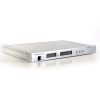
Modbus RS-232 Fiber Optic Converter
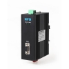
Modbus RS-232 Fiber Optic Converter
Description:
Transmission rate
The HFD-FO-MB Series Modbus fiber optic converters support all the transmission speeds between 0 ~ 115.2Kbbps.The transmission rate is set automatically as soon as the HFD receives a frame. The HFD system is a high transparent low-latency transmission system, this system in many aspects has excellent performance.The fiber-optic repeater HFD supports the any rate.
Signal regeneration
The modules regenerate the signal form and amplitude of the data received. This allows up to 200 HFD Modbus converter to be cascaded.
Segment monitoring at the RS 232 port
Each receiver monitors the RS 232 bus segment connected to it for faulty frames or continuously busy networks. If faulty frames are received by the receiver, or if the network is busy for longer than the maximum permitted send time, forwarding of the received signals is blocked until frames can be received again correctly.
Segment monitoring at the optical line
Each receiver monitors the optical line port connected to it for recive framesand status. If faulty frames are received by the receiver, or no single for longer than the maximum permitted time, forwarding of the received signals is blocked until the port status is ok,frames can be received again correctly.
Network Topologies
The following network topologies can be realized with the HFD Modbus optical converter:
_ Point-to-point topology
_ Multi-drop BUS topology
_ Star topology
_ Redundant ring(DSHR)
Combinations of these basic types are also possible. Lines with two optical fibers are used to create the fiber links for these network topologies.If a malfunction – e.g. a break in a fiber line – makes a high degree of field bus network fail-safety necessary, the availability of the network can be increased using a redundant network configuration.
Line topology
In a line structure, the individual RS232 HFDs are connected together by dual-fiber optical fibers. Modules with one optical port are sufficient at the beginning and end of a line, between which modules with two optical ports are necessary.
If single point-to-point connections are to be built up, this can be achieved using two modules each with one optical port.
Star topology
Several modules are combined to form an active RS232 star coupler. Other modules are connected to this by dual-fiber optical fiber lines. The modules of the star coupler are connected to
one another via the electrical port(electrical star segment).All HFD types for different fiber types can be combined using the electrical star segment.
Modules with one or two optical ports can be used to create an active RS232 star coupler. Modules with one optical port are sufficient for connecting a terminal or an RS 232 bus segment to the active star coupler.
Redundant optical ring
This network topology represents a special form of line topology. A high degree of network operating safety is achieved by ”closing“ the optical line. A redundant optical ring can only be realized with modules with two optical ports of the same type.
An interruption of one or both optical fibers between two modules is detected by the HFD and the ring is transformed into an optical line.If one module fails only those terminals connected to this module or the RS 232 segment are uncoupled from the ring. The remainder of the network itself continues to function as a line. The error is indicated by the LEDs on the two HFD connected to the malfunctioning optical fiber and their signaling contacts. The segmentation is lifted automatically as soon as both modules recognize that the segmented field bus network is functioning correctly with the test frames.
| Voltage/power supply | 5V/12V/24 DC |
| Operating voltage | 12 V to 30 V DC, typ. 24 V, |
| Current consumption | typ. 120 mA@24V |
| Signaling contact | Max .switch DC24V@2A or This email address is being protected from spambots. You need JavaScript enabled to view it. |
| Signal transmission | |
| Transmission rate | 0 – 115.2Kbps |
| Setting transmission rate | Automatic |
| Bit error rate | < 10-9 |
| Transmission principle | Transparent transmission |
| Delay time (Electrical port) | ≤2us/Port |
| Delay(Opticale Fiber Port) | ≤1.6us/Station |
| Retimer (Electrical port) | |
| Input | High speed sampling transmission |
| Single type | NO protocol type |
| Output | Signal distortion < 10ns |
| Edge jitter is less than15ns | |
| Electrical port | |
| Input/output signal | RS 232 level DB9 Connector |
| PIN assignment | 5-PIN terminal block |
| Bus properties(All Segments and Fibles) | |
| The equivalent bus | Yes |
| support for single master system | Yes |
| supports multiple master system | Yes |
| The master station Position | Can be placed on any node |
| Optical ports | |
| Wavelength | SM: 1310 nm, MM: 850 nm |
| optical power | |
| – in glass fiber 9/125um | -9dBm – -18 dBm |
| – in glass fiber G 62.5/125 | -13 dBm – -20 dBm |
| Receiver sensitivity | -34dBm |
| Transmission distance | |
| –with glass fiber 9/125um | 0 – 20,000 m (0.3 dB/km) |
| – with glass fiber G 62,5/125 | 0 – 3,000 m (2.0 dB/km) |
| Connector | ST/FC/SC, ST as the standard |
| Electromagnetic compatibility (EMC) | |
| Limit class B (EN 55022) | EN 61000-4-2 EN 61000-4-3 |
| Burst: | |
|
On power supply lines |
±2 kV (EN 61000-4-4) |
| Surge | |
| Power lines,Shielded RS 232 lines |
±1 kV symmetrical,±2 kV asymmetrical (EN 61000-4-5) |
| Others | |
| Ambient temperature | -25 °C to +75 °C |
| Storage temperature | 40 °C to +85 °C |
| Relative humidity | <95 %, non-condensing |
| Protection class | IP 40 |
| Dimensions (H x W x D) | 120 x 40 x 92 mm |
| Weight | approx. 600 g |
Ordering information:
|
Model Number |
Description |
Fiber No. |
Fiber Mode |
Fiber Connector |
|
HFD-FO-MB2-P1M |
Point to Point Link,Single Fiber(BI-DI), 2km |
1 |
Multi Mode |
ST/SC/FC |
|
HFD-FO-MB2-P2M |
Point to Point Link,Dual Fiber, 2km |
2 |
Multi Mode |
ST/SC/FC |
|
HFD-FO-MB2-P1S |
Point to Point Link,Single Fiber(BI-DI), 20km |
1 |
Single Mode |
ST/SC/FC |
|
HFD-FO-MB2-P2S |
Point to Point Link,Dual Fiber, 20km |
2 |
Single Mode |
ST/SC/FC |
|
|
|
|
|
|
|
HFD-FO-MB2-M2M |
Multi Point Bus Link,Dual Fiber(BI-DI), 2km |
2 |
Multi Mode |
ST/SC/FC |
|
HFD-FO-MB2-M4M |
Multi Point Bus Link,4 Fiber, 2km |
4 |
Multi Mode |
ST/SC/FC |
|
HFD-FO-MB2-M2S |
Multi Point Bus Link,Dual Fiber(BI-DI), 20km |
2 |
Single Mode |
ST/SC/FC |
|
HFD-FO-MB2-M4S |
Multi Point Bus Link,4 Fiber, 20km |
4 |
Single Mode |
ST/SC/FC |
|
|
|
|
|
|
|
HFD-FO-MB2-R2M |
Redundant Ring Link,Dual Fiber(BI-DI), 2km |
2 |
Multi Mode |
ST/SC/FC |
|
HFD-FO-MB2-R4M |
Redundant Ring Link,4 Fiber, 2km |
4 |
Multi Mode |
ST/SC/FC |
|
HFD-FO-MB2-R2S |
Redundant Ring,Dual Fiber(BI-DI), 20km |
2 |
Single Mode |
ST/SC/FC |
|
HFD-FO-MB2-R4S |
Redundant Ring,4 Fiber, 20km |
4 |
Single Mode |
ST/SC/FC |
CAN's Transmission Distance by Copper Cable & Fiber Cable
Because of CAN's cascading feature,CAN'S data baud rate is tighly tied to the transmission distance,through 5 months lab testing,Buenoptic finally worked out the testig results to CAN's transmission distance by fiber optic cable and pair twisted copper cable on different baud rates:
CAN Tansmission Distance:
|
Baud Rate(bit) |
Copper Cable(m) |
Fiber Distance(m) |
Remarks
|
|
1Mbir/s |
25m |
45m |
Lab Condition
|
|
800Kbir/s |
50m |
90m |
Lab Condition
|
|
500Kbir/s |
100m |
180m |
Lab Condition
|
|
250Kbir/s |
250m |
450m |
Lab Condition
|
|
125Kbir/s |
500m |
900m |
Lab Condition
|
|
100Kbir/s |
650m |
1150m(1.15Km) |
Lab Condition
|
|
50Kbir/s |
1000m(1Km) |
1800m(1.8Km) |
Lab Condition
|
|
20Kbir/s |
2500m(2.5Km) |
4500m(4.5Km) |
Lab Condition
|
|
10Kbir/s |
5000m(5Km) |
9000m(9Km) |
Lab Condition
|
|
5Kbir/s |
10000m(10Km) |
20000m(20Km) |
Lab Condition
|
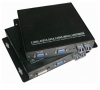
VGA Optical Fiber Converter
Description:
VGA has single mode and multi mode two types and composed of transmitter and receiver; transmit 1 channel VGA signal through one fiber, distance can reach 20km.
Features:
Non-compression
VGA signal transmit on fiber
Support VESA
Support VGA loop out
VGA, DVI output
Specification:
Transmitter
Input interference: 1 channel HD 15F (VGA)
Loop out interference: 1 channel HD 15F (VGA)
Fiber output interference: 4 channels LC(RGB CK)
Receiver
Fiber input interference: 4 channels LC(RGB CK)
Output interference: 1 channel HD 15F (VGA), 1 channel HD 15F (VGA)
Fiber connector: LC
Wavelength: 850nm/1310nm
Distance: 500m/20km
Size: 183mm X 154mm X 30mm
Adaptor: AC 85-265V
Bandwidth: 4.95Gbps (Max)
Resolution: 1920*1200@60Hz
Power consumption: 1920*1200@60Hz
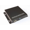
DVI Video Fiber Optical Converters
Description:
The 4-coreS DVI Fiber Optic Video Converter transmits signal over fiber from 10km to 80km,。Transmitter through circuit used for the monitoring of the local computer, the receiver has an output port on the transmitter and receiver LEDs to show power, video and optical signal status .The system of specialized applications in professional A/V, security system, campus environment, industrial monitoring, as well as a large hall (Stadium), and so on, to meet remotely access a computer or video signal. Because data is transmitted through optical fibers, virtually no interference.
Features:
Card version or desktop version available, which is applied to 2U rack mounting
8-bit digital code and non-compression video transmission
Support any high-resolution video signal
5Hz-8MHz video channel
Automatic compatible with PAL, NTSC and SECAM video system
With APC circuit, constant output optical power, and large dynamic range
Kilo mega optical fiber transmission, large capacity, and easy to upgrade
Status indicator light which can monitor it's running status
Support no-damage regenerative trunk of video
Advanced self-adaptive technology, All optical interface and electrical interface is unnecessary to adjust
Industrial design and modularization design make the equipment reliable and flexible
Can automatically restore the fuse of power supply
Full built-in power supply, unique appearance design. External dimensions (95mm*107mm*25mm)
Internal power dissipation: 2.6W (Input: AC 140~260V)
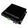
SDI Video Fiber Optical Converter
DESCRIPTION:
The V-SDI series fiber video converter is an ideal and economic solution for broadcasting or surveillance applications. It receives one HD-SDI electrical input, perfectly converts electrical SDI signal to single mode optic SDI signal. It supports transmission image of SDTV (143-540Mbps), HDTV (1.485Gbps) and HDTV (3Gbps, 1080p60).
Both transmitter and receiver provide equalizing and reclocking at input unit in order to re-construct the signal for consistent quality. Besides, with advanced fiber technology, V-SDI can easily pass pathological pattern to prove its complete transmission.
The V-SDI series fiber video converter are typically used in applications where the cameras have P/T/Z capabilities. Plug and Play design ensures the ease of installation and operation. Electronic and optical adjustments are never required. LED indicators are provided for instantly monitoring system status. Devices are available for either standalone or rack-mount installation ,which is suitable for different working environment .
Opitcal:
|
Wavelength |
1310nm&1470nm~1610nm |
|
Output Power |
-10~-3dBm / -3~+2dBm |
|
Optic fiber |
50/125u multimode,62.5/125u multimode,9/125u single mode |
|
Rx sensitivity |
-18dBm |
|
Optical connector |
LC、FC、ST (optional) |
|
Distance |
0~500M (MM) / 0~80KM (SM) |
Data:
|
Data protocol |
RS232、RS422、RS485、Manchester,BIPHASE data |
|
Data rate |
0~200 Kbps |
|
Error rate |
< 10-9 |
|
Connector |
Standard terminal lead |
Video:
|
SDI Input |
||
|
Signal Type SDI |
SMPTE 424M, SMPTE 292M, SMPTE 259M, DVB-ASI |
|
|
Data Rates |
270Mbit/s - 1.48Gbit/s - 3Gbit/s |
|
|
Cable Equalization |
Automatic cable EQ (Belden 1694A cable) 250m @ 270Mbit/s, 140m @ 1.5Gbit/s, 80m @ 3Gbit/s |
|
|
Connector |
BNC 75 Ohm |
|
|
General: |
||
|
Input Power |
5 V DC |
|
|
Power consumption (maximum) |
Transmitter: 1.8W Receiver: 1.5W |
|
|
Operating temperature |
0°C to 55°C |
|
|
Storage temperature |
-10°C to 70°C |
|
|
Operating humidity |
0 ~ 95% (non-condensing) |
|
|
Net Weight |
310g per pair |
|
|
Case material |
Aluminum |
|
Miniature HD SDI to Fiber Optic Converter
Mini SDI Optical Converters
This unique optical cable system is used to transmit the distanced HD-SDI signal by an optical fiber cable. Single optical fiber can quickly transfer the singal for 30km whose data rate reach up to 1.5G, meanwhile SDI singal is supported.
Single singlemode fiber transmission of HD-SDI
The highest video bandwidth: 1.5Gbps.
The highest resolution: 1080P@30Hz.
The longest transmission distance: 20km Small, concise, directly connect to SDI interfaces of source and display devices.
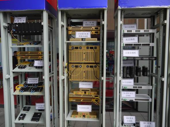
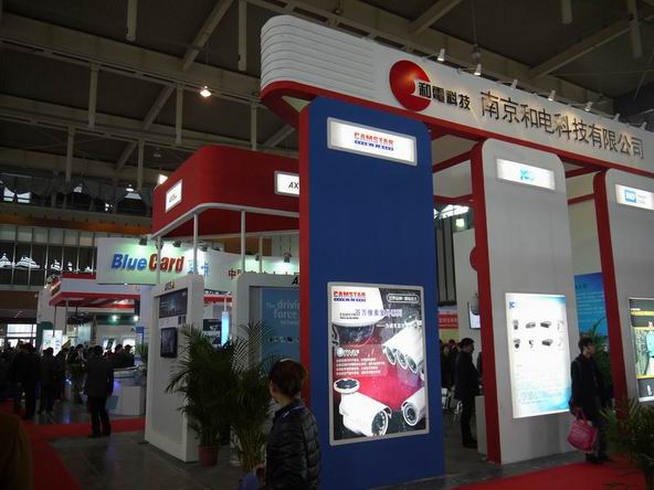
Nanjing Security Exhibiton Held in NJ Expo Center
21st,March,2013.Nanjing International Security Exhibition opened up in Nanjing Exhbition Center,on which more than 300 exhibitors displayed their products.The exhibition mainly include these sections:CCTV system,intelligent video analysis,electronic fence,door access system,fire alarm system,smart homes.A lot of new technoligues debut on this show.
Bueno exhibited fieldbus FO modem series products,industrial ethernet switches and video optical transmitter products on this show and attracted more than 100 vistors to know more about our products.

Catalogue(Product brochure)
The copy right of Buenoptic catalogue is reserved by Bueno Optic Limited,the catalogue can only be used for downloading,reading,marketing and other commercial purposes,any duplicate of our design is prohibited.
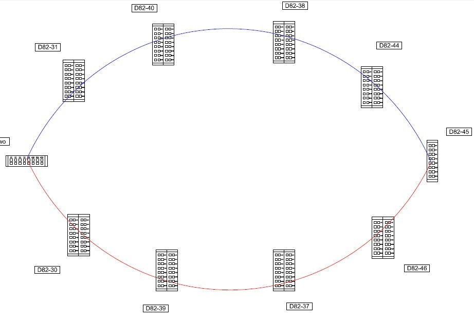
Serial Redundant Ring Fiber Optic modems Used in European Wind Farm
Through years efforts,a medium-sized wind farm was finally completed in Eastern Euope and Bueno RS-485 redundant ring fiber optic modem also became one important part of the wind farm's networks system. The whole project needed 175 pieces of DIN Rail RS-485 redundant ring fiber optic modems to combine a redundant ring fiber optic network.RS-485/232/Ethernet & Profibus redundant ring networks is quite common in power systems(substation,wind farm,solar plant,ect) due to the safety of ring networks.Once one node is faulty, the redundant ring fiber optic modem will start the self-healing recovery function to maintain the normal work of the whole network,thus the whole network will not be influenced by one faulty node and keep working, which is very important for the power grid systems where the safe network is much more important than anything.
The below is one of the the configuration of the project:
GPS TCP/IP Sychronization Time Server
GPS TCP/IP Time Server(LAN output)
The SY series of GPS TCP/IP time servers are specifically for power system, automatizatio system, communicate system and traffic system that need high-precise time requirer.Our system is based on GPS, and the precision of time is 1µs.It can track 12 GPS satellites at the same time, and selects the best satellite automaticly for locating and timing. It outputs 1PPS, 1PPM, 1PPH time pulse and UTC time ,and the synchronous precision is 1µs, and it can measure the industrial frequency, and outputs date, time, cycle clock, cycle, clock difference, safe running days, and so on through RS232 serial with two formats.
Technical parameter:
1. Receiving frequency:1575.42MHZ, it can track 8-12 GPS/BDS satellites at the same time.
2. Antenna radio sentivity:-166dbw, with 30 metres wire. If the wire is not long enough, customer can prolong it by himself by selection of coaxial-cable that attenuation of
1.56GHZ is not more than 0.7db per metre, the attenuation of prolonged cable is not more than 5db.
3. Capture time: from 20 seconds to 2 minutes (Annotate: the outputs of synchronous clock are all isolated by photoelectricity coupling and output 60ns)
4.1PPS output:
Timing varacity: 1µs Voltage: TTL voltage
Polarity: positive pulse Pulse width: about 100ms
Impedence: 50 Ώ Channel number: 1
Fore edge: <20ns
5.1PPM: output:
Timing varacity:: 1µs Voltage: TTL
Polarity: positive pulse Pulse width: about 100ms
Impedence: 50 Ώ Fore edge: <20ns
6.1PPH output:
Timing varacity:: 1µs Voltage: TTL
Polarity: positive pulse Pulse width: about 100ms
Impedence: 50 Ώ Fore edge: <20ns
7.Cycle precision: ±0.001
8.Industry frequency clock: the clock that is promoted by industry electricity is synchronous with standard clock when power is on.
9.Clock difference: that is standard clock minus industry frequency clock,synchronous time difference is zero,precision is 20 ms.
10.Longitude, latitude: where the electric power synchronous clock locates.
11.Display: 14 bits LCD display that includes cycle,date,time,longitude,latitude,industry frequency clock,clock difference (standard clock minus industry frequency clock).
12.RS232: output time code (year, month, day, hour, minute, second), industry frequency clock time(hour, minute, second), clock difference,cycle.
13.RS232: output “ST” format time code (selected by switching circuitry)
14.Power: DC110V, 10%, 15W. AC or DC other power supply is also accepted.
15.Size: standard 1 U Chasis.
16. Support Redundant GPS timing systems.
17. Other optional output: NTP,DB9,Seral 485 terminal,Irig-B,Fiber ST & all other types of connectors.