Sidebar
News Press

Administrator
NARI Substation Automation Projects for MEA Boom in Thailand
Nanjing NARI group won Thailand MEA power company's (Thailand) 20 EPC package for substation monitoring and control system reconstruction project. This is NARI's third consecutive winning Thai MEA substation EPC project, at this point, NARI's construction and renovation of substation EPC project in Thailand has reached 45, market share of more than 30% in Thailand region, broke the Europe and the United States electrical giant monopoly on substation automation system in the region.
NARI's wiinning of the project is currently the largest scale and highest amount of the winning project in Thailand, will use the NARI's independent research and development based on IEC61850 standard NS3000 digital monitoring system products, the project contains the Thailand Bangkok within the jurisdiction of MEA 20 substation automation monitoring system of equipment procurement, design, installation, debugging, etc.
The deposits of around 20 substation all concentrated in the Thai capital of Bangkok, covering the key areas of power supply in BKK.
Digital Relay Protection Device
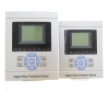
Substation Digital Relay Protection Device(Protection Relay)
Measurement and Control Equipment BPD001A series of protection by the line protection, transformer protection, capacitor protection, reactor protection, standby power from the cast, composed of motor protection, can be used for 110kV and below voltage levels of power grid and power plant auxiliary power system. Through the use of high-performance 32-bit CPU will be protection, monitoring and control, communications functionality in one integrated, fit and substation integrated automatic system or the electrical power plant automation systems. Devices can be installed Group centralized screen can also be directly installed in the switch cabinet to carry out decentralized control.
1.2 Technical Features
1 Overview:
1.1 Main uses and programs:
Using the most popular high-speed processor, Frequency up to 200 MHz, built-in resource-rich, easy external circuit design, product manufacturing quality assurance and stability. Sufficient hardware resources, 4M bytes Flash Memory memory, 8M bytes SDRAM.
With USB interface, available through U disk directly upgrade software, can also put information and fault recorder data moves directly into the U disk to facilitate fault analysis.
Measuring three-phase current and zero-sequence current (Ia, Ib, Ic, I0), three-phase or line voltage (Uan, Ubn, Ucn, Uab, Ubc, Uca), active power P, reactive power Q, power factor cosφ, frequency f, meritorious electricity kWh, reactive power kVarh.
Current, voltage, power, power measurement not only reflects the fundamental value, but also accurately reflect the 2 ~ 13 sub-harmonic, so that the measurement results with a dedicated line measurement meters.
Along with DC 4 ~ 20mA analog output (can be customized for the current, voltage or power) to replace capture transmitter communicate.
Up to 14-channel DI,Users can customize the name.
Way to protect the export of components through the tripping matrix setting, the convenience of users to select the relay action. Contact may choose to export all the relays for tripping contact (automatic return) or signal contact (after reversion back).
Independent Trip circuit adaptive 0.5A ~ 5A switch current Reclosing jump.
GPS options on PPM or PPS, as well as support for IRIG-B time-mode (RS485 interface).
Differential protection to prevent equipment to start or outside the failure resulting in differential protection saturated TA maloperation criterion.
Valid and reliable criterion disconnected PT effectively prevent low-voltage electrical components malfunction.
Two 100M Ethernet communication interface, a RS485 communication interface to support the IEC60870-5-103, Modbus and other protocol.
9 recorder, and each wave contains the 1.9 seconds recorded in the sampling point and the amplitude of waves recorded, the sampling points, the largest recorded wave volume contains the 14-channel analog (interval 1mS), the largest wave amplitude recorded contains 40 analog amplitude and 32 switch (interval 5mS). 2 motor start recorded wave (interval of 100mS), activated before the 1S, after 29S. Wave was recorded using standard Comtrade format.
The full graphical programming technology, as well as stable and reliable protection relay library, improve reliability and correctness of the procedure.
Machine static low power consumption (about 6W), LCD module using the new technology, life expectancy increased substantially.
High anti-interference performance, by 10 Electromagnetic Compatibility Testing & Certification, fast transients, electrostatic discharge, surge anti-interference performance are the highest grade (Ⅳ grade) standard.
Working ambient temperature range: -25 ℃ ~ +55 ℃ (liquid crystal non-fuzzy, slow phenomenon).
1.3 Protection device type and configuration:
|
Device Type |
Function Deployment |
Scope |
|
BPD001A Line Protection |
3-zone composite voltage overcurrent protection / 3-zone directional zero-sequence overcurrent protection / Overload protection / Autoreclose / Manual closing synchro-check / Closing Post-acceleration protection / Low frequency load shedding / Undervoltage load shedding / Lower current ground wire selection / Measurement |
35kV and below the line voltage |
|
BPD001B Line Protection |
3-zone composite voltage overcurrent protection / Zero-sequence overcurrent protection / Overload protection / Post-acceleration protection / 4-20Ma Output / Measurement |
Power into the line, bus coupler switch |
|
BPD001C Transformer Differential Protection |
Differential Protection / Differential instantaneous protection / Differential current overcurrent alarm / TA wire break blocking |
110kV and below voltage levels and higher capacity of the transformer 6300kVA |
|
BPD001D Transformer’s Noumenon Protection |
Transformer’s noumenon protection / Independent Trip circuit |
|
|
BPD001E Transformer Backup Protection |
3-zone composite voltage overcurrent protection / Zero-sequence overcurrent protection / Gap zero-sequence overcurrent protection / Zero-sequence overvoltage protection / Overload protection/ starting ventilation /On-load voltage-regulated blocking / Measurement |
|
|
BPD001F Transformer Protection |
3-zone composite voltage overcurrent protection / Overcurrent inverse time-limit protection /2-zone negative sequence overcurrent protection / HV side zero-sequence overcurrent protection / LV side zero-sequence overcurrent protection / LV side zero-sequence inverse time-limit overcurrent protection / Overload protection / Overvoltage protection / Undervoltage protection / Noumenon protection / FC blocking / 4-20mA output / Measurement |
2000kVA plant the following change, by change, grounding change |
|
BPD001G Capacitor Protection |
Instantaneous overcurrent protection / Overcurrent protection / Overvoltage protection / Undervoltage protection / Zero-sequence overcurrent protection / Neutral unbalance overcurrent protection / Neutral unbalance overvoltage protection / Measurement |
Shunt Capacitor Bank |
|
BPD001H Reactor (cable) Differential Protection |
Differential Protection / Differential instantaneous protection / 3-zone composite voltage overcurrent protection / Zero-sequence overcurrent protection / Overload protection / Measurement |
Series reactor, cable lines |
|
BPD001I Standby Power Supply Automatic Throw-over Equipment |
Bus coupler Automatic Throw-over / Progressive lines Automatic Throw-over / transformer Automatic Throw-over / Service power source Automatic Throw-over |
Standby power Supply Automatic Throw-over Equipment |
|
BPD001J TV Protection |
2-zone undervoltage protection / Busbar insulation Check / Measurement |
35kV and below TV cabinets |
|
BPD001K Motor Integrated Protection |
Instantaneous overcurrent protection / Overcurrent protection / 2-zone negative-sequence overcurrent protection / Negative-sequence inverse time-limit overcurrent / Overheat protection / Rotor-locked protection / Single-phase ground fault protection / Undervoltage protection / Overload protection / Non-electric quantity protection / FC blocking / 4-20mA / Measurement |
Following 2000kW induction motors |
|
BPD001L Motor Differentia And Integrated Protection |
Differential protection + Integrated protection + Measurement |
Asynchronous motor 2000kW and above |
2 Technical performance and indicators:
2.1 Rated electric parameters:
Power supply:
DC rated voltage: 220V or 110V
Permissive variation: -20% ~ +15%
Ripple coefficient: not larger than 5%
Rated current, voltage
AC current: 5A or 1A
AC voltage: 100V or 100/V
2.2 Principal technical indices
Accurate operating range
Current: 0.04In ~ 20In (In = 5A or In = 1A);
Voltage: 1V ~ 140V;
Frequency: 45Hz~55Hz
Measuring accuracy:
Current: Class 0.2
Voltage、Power: Class 0.5
Frequency: ≤±0.01Hz;
4-20mA DC: Class 0.5。
Setting error:
Setting error: no more than ± 3%;
Action time error: set the time limit protection, not more than (± 1% setting value +40) ms; inverse-time protection, not more than ± 5% setting value or ± 40ms.
Telesignalling resolution
Less than 2ms.
GPS:
PPM or PPS:GPS devices provide the interface requirements for air optocoupler, voltage greater than 50V;
IRIG-B:DC Time Code, RS485 interface
Contact capacity:
Operation of circuit tripping current and switch current: 0.5A ~ 5A adaptive;
Trip space contact: 5A (DC220V closure of capacity); signal space contact: 5A (DC220V closing capacity).
2.3 Environmental conditions
Ambient temperature: -25°C ~ +55°C
Relative humidity: 5% ~95% (no condensated dew or ice inside produce)
Atmospheric pressure: 66Kpa ~ 106Kpa
2.4 Power consumption:
AC current circuit: As IN = 5A, not larger than 0.5VA each phase;
As IN = 1A, not larger than 0.3VA each phase;
AC voltage circuit: At rated voltage, not larger 0.5VA each phase;
DC power supply circuit: For normal operation, not larger than 10W;
As the system operates, not larger than 20W
2.5 Overload capability
AC current circuit: at two multiples of rated current, continuous operation; at 10 multiples of rated current, 10s is permitted; at 40 multiples of rated current, 1s is permitted.
AC voltage circuit: at 1.4 multiples of voltage, continuous operation
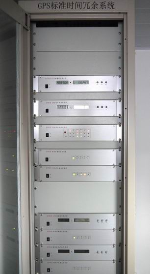
Our GPS Redundancy Time System Mounted to Italy Substations
As an important part of substation automation,GPS time servers are widely used in substations for high accuracy synchronization time. Bueno signed contract with ABB company to provide GPS redundancy time systems to the substation automation project in south Italy.
The redundancy GPS time systems is the safest time system in the world, which can protect the whole time system from being broken by one GPS master clock or GPS antenna's fault.
It provides 3-layer protection,when the power is off, the UPS will transmit electricity to redundant power supplies of GPS master clocks.If one master clock is faulty,the redundant master clock will continue to work automatically immediately.If one GPS antenna lose GPS signal,the other GPS clock will search for GPS source automatically. The redundancy GPS time server system are applied to very important projects that is quite demanding with time accuracy and safety.
GPS IRIG-B & NTP Time Server(2U)
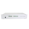
Introduction:
The GPS-2-E-NTP Network Time server provides a high precision time directly to TCP/IP networks using NTP(Network Time Protocol). It synchronizes time of any NTP clients running on remote PC’ s. It supports both NTP and SNTP clients for more of current popular operating systems including: Microsoft Windows 95/98/Me/NT/2K/XP, Linux, FreeBSD, IBM AIX and other UNIX family systems. It can synchronize simultaneously thousands of servers, workstations and routers.
Features:
The GPS-2-E-NTP is high quality professional time server for computing, telecom, military, power grid, traffic systems and other science purposes. It has been manufactured with no mechanical parts as coolers or hard disk. All cooling system has been resolved on natural air circulation outgoing via metal case of unit.
Technology:
NTP : supports all versions of NTP, SNTP including latest release 4.1.1 supporting modes: CLIENT,SERVER, BROADCAST, MULTICAST. Authentication: MD5 with manual/automatic key generation.
SNTP : supports all versions of Simple Network Time Protocol
OS Supports :Windows 95/98/Me/2K/XP/WIN7/CE, OS/2, VAX-11/785 v4.3, HPUX, SunOS, Solaris, MIPS Ultrix, ALPHA OSF/1, SGI IRIX, A/UX, AIX, Sinix, BSD, Linux, Dell SVR4, SCO Unixware, CISCO products.
LAN : 10/100 Based T: RJ-45 connector IEEE 802.3 - shielded data line
IRIG-B: 1x BNC + 1x RS422
RS-485: 2xchannels(serial code)
RS-232: 4xRS232(serial code,DB9 Connector)
PPS: 2 x PPS,2xPPM , 2xPPH ((TTL/ active optical isolation and passive)
Alarm dry contact output: 2 channels(GPS&powerloss),alarm signal can be transmitted to RTU
Chipset :Motorola receiver (8) channel with RAIM
Antenna: BNC1.5GHz / 8m + active converter (IP65 to UTP Cat5. cable 200m. (max.500m), RECEIVER :input frequency 1575.42MHz (L1).
INPUT :110-240V AC/DC,DC48V,DC24V,DC12V
FUSE :1 electronic
OUTPUTS :+5V / 5A, +12V / 0.6A, -12V / 0.5A TOTAL LOAD :60 Watt
Actual power consume: Less than 10W
GPS ACCURACY: better than ±100 nsec after synchronization of first 1 hour better than ±1 µsec during the first hour of operation
NTP Accuracy :Better than 10 msec (with nanosecond kernel) HOUSING :Metal desktop case, 1U/2U/3U/4U
Protection :rating IP20
LCD Display:6 character+8 character .Can display local & UTC time ,longitude, latitude & altitude. The master clock has self-examination function, when the GPS signal is off and the time server system has internal problems,the LCD has error warning and the dry contact alarm outputs will send signal to RTU.
LED indicator: The LED Blinks when GPS signal is off and DC power supply is faulty.
Dual redundant power supplies: 24V DC & 110-220V AC
Temperature : 0~ 70℃
Storage: -40~ 125℃
Humidity: 85% max
Housing Color: Silver
GPS Antenna: 30 meters wire and GPS antenna
Picture of rear panel:

Modbus RTU,Modbus TCP,Modbus ASCII,& Modbus Plus
1. OVERVIEW
Modbus RTU is an open, serial (RS-232 or RS-485) protocol derived from the Master/Slave architecture. It is a widely accepted protocol due to its ease of use and reliability. Modbus RTU is widely used within Building Management Systems (BMS) and Industrial Automation Systems (IAS). This wide acceptance is due in large part to MODBUS RTU’s ease of use.
MODBUS RTU messages are a simple 16-bit CRC (Cyclic-Redundant Checksum). The simplicity of these messages is to ensure reliability. Due to this simplicity, the basic 16-bit MODBUS RTU register structure can be used to pack in floating point, tables, ASCII text, queues, and other unrelated data.
Modbus RTU Protocol Overview
MODBUS is considered an application layer messaging protocol, providing Master/Slave communication between devices connected together through buses or networks. On the OSI model, MODBUS is positioned at level 7. MODBUS is intended to be a request/reply protocol and delivers services specified by function codes. The function codes of MODBUS are elements of MODBUS’ request/reply PDUs (Protocol Data Unit).
In order to build the MODBUS application data unit, the client must initiate a MODBUS transaction. It is the function which informs the server as to which type of action to perform. The format of a request initiated by a Master is established by the MODBUS application protocol. The function code field is then coded into one byte. Only codes within the range of 1 through 255 are considered valid, with 128-255 being reserved for exception responses. When the Master sends a message to the Slave, it is the function code field which informs the server of what type of action to perform.
To define multiple actions, some functions will have sub-function codes added to them. For instance, the Master is able to read the ON/OFF states of a group of discreet outputs or inputs. It could also read/write the data contents of a group of MODBUS registers. When the Master receives the Slave response, the function code field is used by the Slave to indicate either an error-free response or an exception response. The Slave echoes to the request of the initial function code in the case of a normal response.
Data Object Properties
MODBUS RTU packets are only intended to send data; they do not have the capability to send parameters such as point name, resolution, units, etc. If the ability to send such parameters is needed, one should investigate a BACnet, EtherNet/IP, or other modern protocols.
MODBUS RTU versus Other Protocols
Despite the limitations of MODBUS RTU, there are still many good reasons as to why it is still a contender among other industrial automation protocols. For one, MODBUS RTU is much easier to implement than newer protocols and is a dominant force in the market place. MODBUS RTU also requires significantly less memory. To implement MODBUS RTU, you can fit the necessary size of 2Kb on a small 8-bit CPU or PIC processor, whereas with BACnet and EtherNet/IP, you may require 30-100Kb of memory.
MODBUS RTU Address Requirements
Standard MODBUS RTU node addresses are 1-254, with 0 being reserved for broadcast messages and write only. However the 0 address is rarely used due to the fact that there is no confirmation that the message was properly received at the slave node. This doesn’t have much affect if your physical layer is RS-232 as only one node can be implemented anyway. RS-485 limits the number of nodes to 32, though some drivers will allow you to extend the amount.
The difference between MODBUS RTU and MODBUS TCP
The most basic difference between MODBUS RTU and MODBUS TCP (Also known as MODBUS IP, MODBUS EtherNet, and MODBUS TCP/IP) is that MODBUS TCP runs on an Ethernet physical layer and Modbus RTU is a serial level protocol. Modbus TCP also uses a 6 byte header to allow routing.
Bit Structure in the Byte
The Bit of least importance is sent and received first. All devices within the network must interpret each transmitted byte analogously in this manner. There are no methods for automated recognition of baud rates is not assigned and the same baud rate must be utilized by the Server as well as all clients connected to the bus. No specific baud rate is specified by the MODBUS: typical baud rates are 9600 or 19200.
A transmitted Byte is coded as: 8 Bit binary value, hexadecimal 0 - 9 and A - F. The least significant Bit is sent and received first
MODBUS RTU Memory Map
|
Modbus RTU |
Common |
Starting address |
|
Modbus Coils |
Bits, binary values, flags |
00001 |
|
Digital Inputs |
Binary inputs |
10001 |
|
Analog Inputs |
Binary inputs |
30001 |
|
Modbus Registers |
Analog values, variables |
40001 |
The difference between MODBUS RTU and MODBUS/ASCII
There are two basic transmission modes found in serial MODBUS connections, ASCII and RTU. These transmission modes determine the way in which the MODBUS messages are coded. In ASCII format, the messages are readable, whereas in RTU the messages are in binary coding and cannot be read while monitoring. The trade-off is that the RTU messages are a smaller size, which allows for more data exchange in the same time span. One should be aware that all nodes within one MODBUS network must be of the same transmission mode, meaning MODBUS ASCII cannot communicate with MODBUS RTU and vice versa.
In MODBUS/ASCII, messages are encoded with hexadecimal value, represented with comprehensive ASCII characters. The characters used for this encoding are 0…9 and A…F. For every byte of information, two communication-bytes are used because every communication-byte can only define 4 bits in the hexadecimal system. MODBUS RTU, however, exchanges data in binary format where each byte of data is coded in one communication-byte.
The MODBUS messages on a serial connection are not broadcast in plain format. They are constructed in a way that allows receivers an easy way to detect the beginning and end of a message. The characters start and end a frame when in ASCII mode. To flag the start of a message, a colon ‘:’ is used, and each message is ended with a CR/LF combination. MODBUS RTU uses a different method. In RTU, framing is constructed by measuring gaps of silence on the communication line. Before each message, there must be a minimum gap of 3.5 characters. To prepare for new messages, the receiver clears the buffer when a gap of 1.5 characters is detected. One of the main differences between MODBUS/ASCII and MODBUS RTU is that ASCII allows gaps between the bytes of a message with a maximum length of 1 second. With MODBUS RTU, continuous streams of messages must be sent.
Properties of Modbus/ASCII and Modbus/RTU
|
|
Modbus/ASCII |
Modbus/RTU |
||
|
Characters |
ASCII 0...9 and A..F |
Binary 0...255 |
||
|
Error check |
LRC Longitudinal Redundancy Check |
CRC Cyclic Redundancy Check |
||
|
Frame start |
character ':' |
3.5 chars silence |
||
|
Frame end |
characters CR/LF |
3.5 chars silence |
||
|
Gaps in message |
1 sec |
1.5 times char length |
||
|
Start bit |
1 |
1 |
||
|
Data bits |
7 |
8 |
||
|
Parity |
even/odd |
none |
even/odd |
none |
|
Stop bits |
1 |
2 |
1 |
2 |
About Modbus Plus(MB+)
Modbus Plus was originally developed by Schneider and Modicon and is today managed by the Modbus-IDA user organization. It is a global Fieldbus network with its main application area in Europe and in automation systems from Schneider and Modicon. Modbus-Plus connectivity is available for many different products such as PLC's, Inverters, Drives and I/Os. Modbus Plus is a Master/Slave Fieldbus based on RS-485 transmission technology and a token passing protocol for industrial control applications. Networked devices can exchange messages for the control and monitoring of processes at remote locations in the industrial plant.
The network also provides an efficient means for servicing input/output subsystems. Modicon Modbus Plus Distributed I/O (DIO) Drop Adapters and Terminal Block I/O (TIO) modules can be placed at remote I/O sites to allow the application to control field devices over the network link.
MODBUS PLUS FACTS
Network Type: Master/Slave Fieldbus based on RS-485 with Token passing
Topology: Line topology with segments of up to 32 stations
Installation: Shielded twisted pair cable with 9-pole D-Sub connector.
Cable length per Segment up to 500m extendible with repeaters up to 2.000m.
Speed : 2 Mbit/s
max. Stations : 64
Data: cyclic I/O and acyclic parameter data
Network Features : Master/Slave Fieldbus network for Real-Time control applications.
User Organization: Modbus-IDA User Group
Difference between DeviceNet & CAN
The best way to understand how these two specifications are related is to refer to the Open System Interconnection (OSI) model. The OSI model specifies a seven layer framework for implementing communication protocols, which is shown as follows from top to bottom:
| Application Layer |
| Presentation Layer |
| Session Layer |
| Transport Layer |
| Network Layer |
| Data-Link Layer |
| Physical Layer |
The CAN specification defines the Physical and Data-link layers of the communication system. The CAN specification was developed by Bosch (ISO 11898-1) and fully defines the Data link layer. There are different standards for the CAN physical layer (refer to the link below). Using the CAN specification, the network designer has the means to transmit and receive frames from the CAN bus. It is up to the designer to specify how is the data going to be transferred using frames.
The CAN specification provides a robust communication channel with built-in error detection and confinement. DeviceNet uses the CAN standard as the foundation for a higher level communication protocol. DeviceNet is often referred to as a CAN application layer protocol. The main goal of the DeviceNet specification is to allow interconnection and interchangeability between DeviceNet devices from different vendors. To accomplish that goal DeviceNet defines the following:
- CAN Physical Layer - A single standard is defined for the CAN physical connections. The standard used is High-speed CAN (ISO 11898-2). The specification also includes the bus power voltages, number of devices that can be connected, the types of connectors allowed, cable lengths and baud rates.
- CAN Data Link Layer - The specification is left unchanged. The standard CAN controllers (Intel 82527, for example) can be used with DeviceNet devices.
- Application layer - The main contribution of the DeviceNet specification is the way data is organized and transferred between devices. DeviceNet specifies an object model that devices need to implement. This way all devices present a consistent interface to the rest of the network, hiding the internal details of the device.
In terms of application programming, a developer writing an application using NI-CAN will manipulate frames and needs to have detailed knowledge of the other devices in the network, to be able to address them using the arbitration IDs. This is sufficient for small, "closed" networks, such as an automobile network, where the main goal is a fast and extremely reliable communication network.
Using NI-DNET, the developer opens communication objects with other devices on the network. The DeviceNet specifications provides the means to detect the devices on the network and route messages from one node to the other. In this case, the NI-DNET driver is capable of communicating with any DeviceNet compliant device. This allows for functionally equal devices from different vendors to be interchangeable.
There are other CAN application layer protocols, such as: CAL (CAN Application Layer), CANopen, PCAL, SDS (Smart Distributed System) and CAN Kingdom. National Instruments products only support DeviceNet.
Design for SG Foreign Ministry Anti-access System

LC Multi Mode Patch Cord
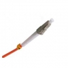
LC Fiber Optic Patch Cords are comprised of a polymer outer body and inner assembly fitted with a precision alignment mechanism. The combination of a ceramic/phosphor bronze alignment sleeves and precision molded polymer housing provides consistent long-term mechanical and optical performance.
LC fiber patch cord available for PC/UPC/APC version, provide both SM, MM, simplex and duplex, 0.9mm, 2.0mm, 3.0mm cable diameter for choose, different fiber length by customers request.
Description
Cable Color: Orange
Fiber counts: 1 Fiber (Simplex)
Fiber type: Multimode (50/125um or 62.5/125um)
Connector type: LC
Connector counts: 2 connectors
Application
¨ Telecommunication
¨ CATV, FTTH, LAN
¨ Fiber oiptic sensors
¨ Optical transmission system
¨ Test equipment
Features
¨ High dense spaces
¨ Ceramic ferrules connectors
¨ Half the size of standard connector
¨ Low insertion loss, high return loss
¨ Excellent mechanical endurance
¨ High credibility and stability
¨ Good in repeatability and exchangeability
¨ 100% Insertion, Return Loss, End Face and Interference inspection
Technical Data
|
Parameter |
Unit |
FC, SC, LC |
ST, MU |
MTRJ, MPO |
E2000 |
||||||||
|
SM |
MM |
SM |
MM |
SM |
MM |
SM |
|||||||
|
PC |
UPC |
APC |
PC |
PC |
UPC |
PC |
PC |
UPC |
PC |
PC |
APC |
||
|
Insertion Loss |
dB |
≤0.3 |
≤0.2 |
≤0.3 |
≤0.2 |
≤0.3 |
≤0.2 |
≤0.2 |
≤0.3 |
≤0.2 |
≤0.2 |
≤0.3 |
≤0.3 |
|
Return Loss |
dB |
≥45 |
≥50 |
≥60 |
≥30 |
≥45 |
≥50 |
≥30 |
≥45 |
≥50 |
≥35 |
≥55 |
≥75 |
|
Repeatability |
dB |
≤0.1 |
|||||||||||
|
Durability |
dB |
≤0.2dB typical change, 1000 matings |
|||||||||||
|
Operating temperature |
℃ |
-20 ~ +75 |
|||||||||||
|
Storage temperature |
℃ |
-40 ~ +85 |
|||||||||||
Ordering Informaion
|
Connector |
Fiber Core |
Cable Diameter |
Fiber Type |
Polishing |
Cable Jacket |
Cable Color |
Fiber Length |
|
LC SC FC ST D4 MU DIN SMA MPO MTRJ E2000 … |
Simplex Duplex |
0.9mm 2.0mm 3.0mm |
SM:9/125um MM:50/125um MM:62.5/125um OM3 |
PC UPC APC |
PVC LSZH |
Yellow Orange Aqua others |
1M 2M 3M … 10M 20M 30M … |
LC Single Mode Patch Cord
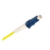
LC Fiber Optic Patch Cords are comprised of a polymer outer body and inner assembly fitted with a precision alignment mechanism. The combination of a ceramic/phosphor bronze alignment sleeves and precision molded polymer housing provides consistent long-term mechanical and optical performance.
LC fiber patch cord available for PC/UPC/APC version, provide both SM, MM, simplex and duplex, 0.9mm, 2.0mm, 3.0mm cable diameter for choose, different fiber length by customers request.
Description
Cable Color: Yellow
Fiber counts: 1 Fiber (Simplex)
Fiber type: Singlemode 9/125um
Connector type: LC
Connector counts: 2 connectors
Application
¨ Telecommunication
¨ CATV, FTTH, LAN
¨ Fiber oiptic sensors
¨ Optical transmission system
¨ Test equipment
Features
¨ High dense spaces
¨ Ceramic ferrules connectors
¨ Half the size of standard connector
¨ Low insertion loss, high return loss
¨ Excellent mechanical endurance
¨ High credibility and stability
¨ Good in repeatability and exchangeability
¨ 100% Insertion, Return Loss, End Face and Interference inspection
Technical Data
|
Parameter |
Unit |
FC, SC, LC |
ST, MU |
MTRJ, MPO |
E2000 |
||||||||
|
SM |
MM |
SM |
MM |
SM |
MM |
SM |
|||||||
|
PC |
UPC |
APC |
PC |
PC |
UPC |
PC |
PC |
UPC |
PC |
PC |
APC |
||
|
Insertion Loss |
dB |
≤0.3 |
≤0.2 |
≤0.3 |
≤0.2 |
≤0.3 |
≤0.2 |
≤0.2 |
≤0.3 |
≤0.2 |
≤0.2 |
≤0.3 |
≤0.3 |
|
Return Loss |
dB |
≥45 |
≥50 |
≥60 |
≥30 |
≥45 |
≥50 |
≥30 |
≥45 |
≥50 |
≥35 |
≥55 |
≥75 |
|
Repeatability |
dB |
≤0.1 |
|||||||||||
|
Durability |
dB |
≤0.2dB typical change, 1000 matings |
|||||||||||
|
Operating temperature |
℃ |
-20 ~ +75 |
|||||||||||
|
Storage temperature |
℃ |
-40 ~ +85 |
|||||||||||
Ordering Informaion
|
Connector |
Fiber Core |
Cable Diameter |
Fiber Type |
Polishing |
Cable Jacket |
Cable Color |
Fiber Length |
|
LC SC FC ST D4 MU DIN SMA MPO MTRJ E2000 … |
Simplex Duplex |
0.9mm 2.0mm 3.0mm |
SM:9/125um MM:50/125um MM:62.5/125um OM3 |
PC UPC APC |
PVC LSZH |
Yellow Orange Aqua others |
1M 2M 3M … 10M 20M 30M … |
FC Multi Mode Patch Cord
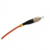
FC fiber optic patch cord features low cost, simplicity as well as good durability, the ceramic ferrules make them accurate alignment. FC fiber optic patch cord are with a locking tab on the cable termination, they are push and pull type fiber optic connectors. Generally FC fiber optic patch cord life cycle is about one thousand times mating cycle.
FC fiber patch cord available for PC/UPC/APC version, provide both SM and MM, 0.9mm, 2.0mm, 3.0mm cable diameter for choose, different fiber length by customers’ request.
Description
Cable Color: Orange
Fiber counts: 1Fiber (Simplex)
Fiber type: Multimode (50/125um or 62.5/125um)
Connector type: FC
Connector counts: 2 connectors
Application
¨ Telecommunication
¨ CATV, FTTH, LAN
¨ Fiber oiptic sensors
¨ Optical transmission system
¨ Test equipment
Features
¨ Screw-thread coupling mechanism
¨ Ceramic ferrules connectors
¨ Low insertion loss, high return loss
¨ Excellent mechanical endurance
¨ High credibility and stability
¨ Good in repeatability and exchangeability
¨ 100% Insertion, Return Loss, End Face and Interference inspection
Technical Data
|
Parameter |
Unit |
FC, SC, LC |
ST, MU |
MTRJ, MPO |
E2000 |
||||||||
|
SM |
MM |
SM |
MM |
SM |
MM |
SM |
|||||||
|
PC |
UPC |
APC |
PC |
PC |
UPC |
PC |
PC |
UPC |
PC |
PC |
APC |
||
|
Insertion Loss |
dB |
≤0.3 |
≤0.2 |
≤0.3 |
≤0.2 |
≤0.3 |
≤0.2 |
≤0.2 |
≤0.3 |
≤0.2 |
≤0.2 |
≤0.3 |
≤0.3 |
|
Return Loss |
dB |
≥45 |
≥50 |
≥60 |
≥30 |
≥45 |
≥50 |
≥30 |
≥45 |
≥50 |
≥35 |
≥55 |
≥75 |
|
Repeatability |
dB |
≤0.1 |
|||||||||||
|
Durability |
dB |
≤0.2dB typical change, 1000 matings |
|||||||||||
|
Operating temperature |
℃ |
-20 ~ +75 |
|||||||||||
|
Storage temperature |
℃ |
-40 ~ +85 |
|||||||||||
Ordering Informaion
|
Connector |
Fiber Core |
Cable Diameter |
Fiber Type |
Polishing |
Cable Jacket |
Cable Color |
Fiber Length |
|
LC SC FC ST D4 MU DIN SMA MPO MTRJ E2000 … |
Simplex Duplex |
0.9mm 2.0mm 3.0mm |
SM:9/125um MM:50/125um MM:62.5/125um OM3 |
PC UPC APC |
PVC LSZH |
Yellow Orange Aqua others |
1M 2M 3M … 10M 20M 30M … |