Sidebar
News Press

Administrator
S908 Remote I/O(RIO) Fiber Optic Converter
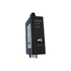
S908 Remote I/O(RIO) Fiber Optic Converter
Description:
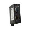
S908 RIO Fiber Optic Converters are designed to be used in Modicon field bus optical repeater. They enable electrical Remote I/O interfaces to be converted into optical interfaces.
Electrical connection to the Remote I/O network is through an “F”–style connector and external Modicon Remote I/O 14 db tap.
By profiting from the familiar advantages of optical transmission technology, the modules can be integrated into existing Remote I/O bus networks. A complete S908 Remote I/O field bus network with modules in point to point, line, star or ring topology, and an arbitrary combination of these, can also be built up.
The redundant ring is also supported, thereby increasing the fail-safety of the field bus network.
The device is powered by 24V DC voltage. A redundant feed increases operational safety.
6 multicolored LED indicate the current operating status
Specifications:
| Voltage/power supply | |
| Operating voltage | 12 V to 30 V DC, typ. 24 V, |
| Current consumption | typ. 120 mA@24V |
| Signaling contact | Max .switch DC24V@2A or This email address is being protected from spambots. You need JavaScript enabled to view it. |
| Signal transmission | |
| Transmission rate | S908 Remote IO |
| Bit error rate | < 10-9 |
| Signal processing time (Opticale Fiber Port) | ≤1.6us/Station |
| Retimer (Electrical port) | |
| Pulse Width Distortion/Jitter | ±10ns(Cascade 50 modules) |
| Cascade modules | 50 |
| Electrical port | |
| Input/output signal | S908 Remote IO |
| Isolate voltage | >= 1500VDC |
| PIN assignment | S908 Remote IO via "F" connector |
| Optical ports | |
| Wavelength | 1310 nm |
| optical power | |
| – in glass fiber 9/125um | -9dBm – -18 dBm |
| – in glass fiber G 62.5/125 | -13 dBm – -20 dBm |
| Receiver sensitivity | -34dBm |
| Transmission distance | |
| –with glass fiber 9/125um | 0 – 20,000 m (0.3 dB/km) |
| – with glass fiber G 62,5/125 | 0 – 3,000 m (2.0 dB/km) |
| Connector | ST |
| Electromagnetic compatibility (EMC) | |
| Limit class B (EN 55022) | EN 61000-4-2 EN 61000-4-3 |
| Burst: | |
|
On power supply lines |
±2 kV (EN 61000-4-4) |
| Surge | |
| Power lines,Cable lines |
±1 kV symmetrical,±2 kV asymmetrical (EN 61000-4-5) |
| Others | |
| Ambient temperature | -25 °C to +75 °C |
| Storage temperature | 40 °C to +85 °C |
| Relative humidity | <95 %, non-condensing |
| Protection class | IP 40 |
| Dimensions (W x H x D) | 62 x 132 x 120 mm |
| Weight | approx. 600 g |
Ordering Information:
|
Model Number |
Description |
Fiber No. |
Fiber Mode |
Fiber Connector |
|
HFD-FO-908-P1M |
Point to Point Link,Single Fiber(BI-DI), 2km |
1 |
Multi Mode |
ST/SC/FC |
|
HFD-FO-908-P2M |
Point to Point Link,Dual Fiber, 2km |
2 |
Multi Mode |
ST/SC/FC |
|
HFD-FO-908-P1S |
Point to Point Link,Single Fiber(BI-DI), 20km |
1 |
Single Mode |
ST/SC/FC |
|
HFD-FO-908-P2S |
Point to Point Link,Dual Fiber, 20km |
2 |
Single Mode |
ST/SC/FC |
|
|
|
|
|
|
|
HFD-FO-908-M2M |
Multi Point Bus Link,Dual Fiber(BI-DI), 2km |
2 |
Multi Mode |
ST/SC/FC |
|
HFD-FO-908-M4M |
Multi Point Bus Link,4 Fiber, 2km |
4 |
Multi Mode |
ST/SC/FC |
|
HFD-FO-908-M2S |
Multi Point Bus Link,Dual Fiber(BI-DI), 20km |
2 |
Single Mode |
ST/SC/FC |
|
HFD-FO-908-M4S |
Multi Point Bus Link,4 Fiber, 20km |
4 |
Single Mode |
ST/SC/FC |
|
|
|
|
|
|
|
HFD-FO-908-R2M |
Redundant Ring Link,Dual Fiber(BI-DI), 2km |
2 |
Multi Mode |
ST/SC/FC |
|
HFD-FO-908-R4M |
Redundant Ring Link,4 Fiber, 2km |
4 |
Multi Mode |
ST/SC/FC |
|
HFD-FO-908-R2S |
Redundant Ring,Dual Fiber(BI-DI), 20km |
2 |
Single Mode |
ST/SC/FC |
|
HFD-FO-908-R4S |
Redundant Ring,4 Fiber, 20km |
4 |
Single Mode |
ST/SC/FC |
GE GENIUS Fiber Optic Converter
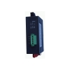
GE GENIUS Bus Fiber Optic Converter
Description:
The GE Genius Fiber Optic Converter is designed for use in optical Genius bus field bus networks. It permits conversions of electrical Genius bus interfaces into optical Genius bus interfaces and vice versa. The repeaters can be integrated in existing Genius bus field bus networks. Genius Fiber Converter can also be used to configure a complete Genius bus field bus network with point to point, line or ring topology.The mechanical structure comprises a compact, rigid metal housing which can either be mounted on a hat rail or on any flat base. Apart from setting the data rate, no other adjustments have to be made during set-up.
*Notes: This transmission distance of network are also affected by the Genius network protocol on Genius network total length constraint
By profiting from the familiar advantages of optical transmission technology, the modules can be integrated into existing GENIUS field bus networks. A complete GENIUS field bus network with modules in pint to point, line, star or ring topology, and an arbitrary combination of these, can also be built up.
The redundant ring is also supported to the GE GENIUS Fiber Optic Converter, thereby increasing the fail-safety of the field bus network.
The device is powered by 24V DC voltage. A redundant feed increases operational safety.
The optical fibers are connected using ST connectors.
6 multicolored LED indicate the current operating status
Transmission rate of the GENIUS Fiber Optic Converter
The Genius fiber optic converter supports the data rates 153.6 kBaud (standard and extended),
76.8 kBaud, and 38.4 kBaud.
Technical Specs:
| Voltage/power supply | |
| Operating voltage | 12 V to 30 V DC, typ. 24 V, |
| Current consumption | typ. 120 mA@24V |
| Signaling contact | Max .switch DC24V@2A or This email address is being protected from spambots. You need JavaScript enabled to view it. |
| Signal transmission | |
| Transmission rate | 153.6Kbps STD, 153.6Kbps EXT 76.8Kbps,38.4Kbps |
| Setting transmission rate | Switch setting |
| Bit error rate | < 10-9 |
| Signal processing time | 80ns/station |
| Cascade modules | 32 |
| Electrical port | |
| Input/output signal | Genius |
| Isolate voltage | >= 1500VDC |
| PIN assignment | 5-PIN terminal block |
| Length of Genius cable | 153.6Kbps STD: <300M 153.6Kbps EXT: <300M 76.8Kbps: <600M 38.4Kbps: < 1200M |
| Connection capability | Max.10 terminal data devices |
| Terminator | Must be attached outside to connector |
| Electrical isolation | |
| – Shielding in/Shielding out | Yes |
| – Data lines/Housing | Yes |
| Optical ports | |
| Wavelength | 1310 nm |
| optical power | |
| – in glass fiber 9/125um | -9dBm – -18 dBm |
| – in glass fiber G 62.5/125 | -13 dBm – -20 dBm |
| Receiver sensitivity | -34dBm |
| Transmission distance | |
| –with glass fiber 9/125um | 0 – 20,000 m (0.3 dB/km) |
| – with glass fiber G 62,5/125 | 0 – 3,000 m (2.0 dB/km) |
| Connector | ST |
| Electromagnetic compatibility (EMC) | |
| Limit class B (EN 55022) | EN 61000-4-2 EN 61000-4-3 |
| Burst: | |
|
On power supply lines |
±2 kV (EN 61000-4-4) |
| Surge | |
| Power lines,Shielded cable lines |
±1 kV symmetrical,±2 kV asymmetrical (EN 61000-4-5) |
| Others | |
| Ambient temperature | -25 °C to +75 °C |
| Storage temperature | 40 °C to +85 °C |
| Relative humidity | <95 %, non-condensing |
| Protection class | IP 40 |
| Dimensions (W x H x D) | 62 x 132 x 120 mm |
| Weight | approx. 600 g |
Ordering Information:
|
Model Number |
Description |
Fiber No. |
Fiber Mode |
Fiber Connector |
|
HFD-FO-GE-P1M |
Point to Point Link,Single Fiber(BI-DI), 2km |
1 |
Multi Mode |
ST/SC/FC |
|
HFD-FO-GE-P2M |
Point to Point Link,Dual Fiber, 2km |
2 |
Multi Mode |
ST/SC/FC |
|
HFD-FO-GE-P1S |
Point to Point Link,Single Fiber(BI-DI), 20km |
1 |
Single Mode |
ST/SC/FC |
|
HFD-FO-GE-P2S |
Point to Point Link,Dual Fiber, 20km |
2 |
Single Mode |
ST/SC/FC |
|
|
|
|
|
|
|
HFD-FO-GE-M2M |
Multi Point Bus Link,Dual Fiber(BI-DI), 2km |
2 |
Multi Mode |
ST/SC/FC |
|
HFD-FO-GE-M4M |
Multi Point Bus Link,4 Fiber, 2km |
4 |
Multi Mode |
ST/SC/FC |
|
HFD-FO-GE-M2S |
Multi Point Bus Link,Dual Fiber(BI-DI), 20km |
2 |
Single Mode |
ST/SC/FC |
|
HFD-FO-GE-M4S |
Multi Point Bus Link,4 Fiber, 20km |
4 |
Single Mode |
ST/SC/FC |
|
|
|
|
|
|
|
HFD-FO-GE-R2M |
Redundant Ring Link,Dual Fiber(BI-DI), 2km |
2 |
Multi Mode |
ST/SC/FC |
|
HFD-FO-GE-R4M |
Redundant Ring Link,4 Fiber, 2km |
4 |
Multi Mode |
ST/SC/FC |
|
HFD-FO-GE-R2S |
Redundant Ring,Dual Fiber(BI-DI), 20km |
2 |
Single Mode |
ST/SC/FC |
|
HFD-FO-GE-R4S |
Redundant Ring,4 Fiber, 20km |
4 |
Single Mode |
ST/SC/FC |
ControlNet Fiber Optic Converter
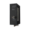
Controlnet Fiber Optic Converter
Introduction
HFD-FO-CL ControlNet Fiber Optic Converters are designed to be used in optical CONTROLNET field bus networks . They enable electrical CONTROLNET interfaces to be converted into optical interfaces.
The ControlNet Fiber Optic Converter can show the different methods for connecting the modules, and the optical ranges of port
By profiting from the familiar advantages of optical transmission technology, the modules can be integrated into existing CONTROLNET field bus networks. A complete CONTROLNET field bus network with modules in point to point, line, star or ring topology, and an arbitrary combination of these, can also be built up.
The redundant ring is also supported to the ControlNet Fiber Optic Converter, thereby increasing the fail-safety of the field bus network.
The device(ControlNet Fiber Optic Converter) is powered by 24V DC voltage. A redundant feed increases operational safety.
The electric port is a BNC socket. An electrical coax segment with the CONTROLNET standard can be connected to this port by drop cable.
The optical fibers are connected using ST connectors.
6 multicolored LED indicate the current operating status
Signal regeneration
The modules regenerate the signal form and amplitude of the data received. This allows up to 50 CONTROLNET to be cascaded.
Segment monitoring at the cable port
Each receiver monitors the cable bus segment connected to it for faulty frames or continuously busy networks. If faulty frames are received by the receiver, or if the network is busy for longer than the maximum permitted send time, forwarding of the received signals is blocked until frames can be received again correctly, or if no signal is received 0.5s.
Segment monitoring at the optical line
Each receiver monitors the optical line port connected to it for recive framesand status. If faulty status are received by the receiver, or no single for recived, forwarding of the received signals is blocked until the port status is ok,frames can be received again correctly.
Specifications:
| Voltage/power supply | |
| Operating voltage | 12 V to 30 V DC, typ. 24 V, |
| Current consumption | typ. 120 mA@24V |
| Signaling contact | Max .switch DC24V@2A or This email address is being protected from spambots. You need JavaScript enabled to view it. |
| Signal transmission | |
| Transmission rate | CONTROLNET rate |
| Bit error rate | < 10-9 |
| Delay time valus(NS2504xx) | 930ns/2 station |
| Delay time valus(NS2501xx,in line topology) |
170ns * (N -2) + 1100ns |
| Delay time valus(NS2501xx,in ring topology) | 170ns * N + 1100ns N = all stations in the network |
| Retimer (Electrical port) | |
| Input | Signal distortion ±30 % |
| Bit length | ±0.12 % |
| Output | Mean bit length ±0.01 % |
| Cascade modules | 50 |
| Electrical port | |
| Input/output signal | CONTROLNET |
| Isolate voltage | >= 1500VDC |
| PIN assignment | BNC |
| Optical ports | |
| Wavelength | 1310 nm |
| optical power | |
| – in glass fiber 9/125um | -9dBm – -18 dBm |
| – in glass fiber G 62.5/125 | -13 dBm – -20 dBm |
| Receiver sensitivity | -34dBm |
| Transmission distance | |
| –with glass fiber 9/125um | 0 – 20,000 m (0.3 dB/km) |
| – with glass fiber G 62,5/125 | 0 – 3,000 m (2.0 dB/km) |
| Connector | ST |
| Electromagnetic compatibility (EMC) | |
| Limit class B (EN 55022) | EN 61000-4-2 EN 61000-4-3 |
| Burst: | |
|
On power supply lines |
±2 kV (EN 61000-4-4) |
| Surge | |
| Power lines,Shielded RS 485 lines |
±1 kV symmetrical,±2 kV asymmetrical (EN 61000-4-5) |
| Others | |
| Ambient temperature | -25 °C to +75 °C |
| Storage temperature | 40 °C to +85 °C |
| Relative humidity | <95 %, non-condensing |
| Protection class | IP 40 |
| Dimensions (W x H x D) | 62 x 132 x 120 mm |
| Weight | approx. 600 g |
Ordering Information:
|
Model Number |
Description |
Fiber No. |
Fiber Mode |
Fiber Connector |
|
HFD-FO-CL-P1M |
Point to Point Link,Single Fiber(BI-DI), 2km |
1 |
Multi Mode |
ST/SC/FC |
|
HFD-FO-CL-P2M |
Point to Point Link,Dual Fiber, 2km |
2 |
Multi Mode |
ST/SC/FC |
|
HFD-FO-CL-P1S |
Point to Point Link,Single Fiber(BI-DI), 20km |
1 |
Single Mode |
ST/SC/FC |
|
HFD-FO-CL-P2S |
Point to Point Link,Dual Fiber, 20km |
2 |
Single Mode |
ST/SC/FC |
|
|
|
|
|
|
|
HFD-FO-CL-M2M |
Multi Point Link,Dual Fiber(BI-DI), 2km |
2 |
Multi Mode |
ST/SC/FC |
|
HFD-FO-CL-M4M |
Multi Point Link,4 Fiber, 2km |
4 |
Multi Mode |
ST/SC/FC |
|
HFD-FO-CL-M2S |
Multi Point Link,Dual Fiber(BI-DI), 20km |
2 |
Single Mode |
ST/SC/FC |
|
HFD-FO-CL-M4S |
Multi Point Link,4 Fiber, 20km |
4 |
Single Mode |
ST/SC/FC |
|
|
|
|
|
|
|
HFD-FO-CL-R2M |
Redundant Ring Link,Dual Fiber(BI-DI), 2km |
2 |
Multi Mode |
ST/SC/FC |
|
HFD-FO-CL-R4M |
Redundant Ring Link,4 Fiber, 2km |
4 |
Multi Mode |
ST/SC/FC |
|
HFD-FO-CL-R2S |
Redundant Ring,Dual Fiber(BI-DI), 20km |
2 |
Single Mode |
ST/SC/FC |
|
HFD-FO-CL-R4S |
Redundant Ring,4 Fiber, 20km |
4 |
Single Mode |
ST/SC/FC |
Profibus PA/FF H1 Distributor
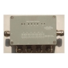
Profibus PA/FF H1 Distributor
Introduction
Now, BFPD (101, 102... Topology connection mode.) the main – spur of the instrument and the most popular among. The trunk line, transport energy and data to the scene. And then distributed to each branch, The BFPD can fieldbus devices (PROFIBUS PA device or FF H1 device), such as measuring instrument, sensor, actuator is connected to the main line of Fieldbus through the branch cable, its installation in the field instruments near branch cable up to 120 meters, usually 60 meters.
The BFPD series products are of three types: 101, 102, 103; each has two main lines of the interface of T1 and T2, 4 spur of X1, X2, X3, X4 interface port; waterproof casing with metal die-casting, protection grade is IP67, installation is simple and convenient, and has a ground terminal for NSPFD; with the BFPD products are 8 LED lights, indicating the operation state of port
Funcion
- Connection of field device (Profibus PA device or FF H1 device) for corresponding bus (PROFIBUS PA or FF H1)
- Automatic termination resistor (103) or a built-in switch-setting termination resistor (102, 101)
- Spur port fault · isolation (103, 102)
- Connection of isolated spue port after fault rectification (103, 102)
- 2 cable glands for the main line
- 4 cable glands for field device
- Connection of the main line and the spur lines via the cage-clamp method (103, 102)
- Revers polarity protection connections
- Port status indicator (103, 102)
- Power supply via the bus
- Screw gland on substrate or mount with adapter on mounting rail
- Degree of protection IP66 ·
- Grounding terminal outside
|
Model |
Description |
|
BFPD101 |
Economic type distributor for FF H1 or PROFIBUS PA, which can set terminal resistance, has two main lines of the interface of T1 and T2, 4 spur of X1, X2, X3, X4 interface port; waterproof casing with metal die-casting, protection grade is IP67, installation is simple and convenient |
|
BFPD102 |
Standard bus distributorfor for FF H1 or PROFIBUS PA,Spur port protection function distributor ,LED indicate the working status of each port, has two main lines of the interface of T1 and T2, 4 spur of X1, X2, X3, X4 interface port; waterproof casing with metal die-casting, protection grade is IP67, installation is simple and convenient |
|
BFPD103 |
High performance bus distributorfor FF H1 or PROFIBUS PA,Trunk cable short circuit protection,Automatic terminal resistance function,Spur port protection function distributor,LED indicate the working status of each port, has two main lines of the interface of T1 and T2, 4 spur of X1, X2, X3, X4 interface port; waterproof casing with metal die-casting, protection grade is IP67, installation is simple and convenient |
Technical Specification:
Power loss:......................................................250 mW
Trunk:
Rated voltage:........................................12~ 32 V DC
Rated current:........................................ <= 3A
Outputs(102,103)
Rated voltage:....................................... <= DC31V
Rated current:....................................... <= 40 mA
Short-circuit current............................... about 55mA
Power failure bypass…………………… 5ms
Current consumption............................. max. 20 mA(NSAFD)
Current consumption............................. max. 8 mA(NSPFD)
Terminating impedance......................... 100 OHM
Overvoltage protection.......................... typ. 39 V
Status,LEDs
Status main line T1,T2………………….. Green LED
No connected main line T1,T2…………. Not lit
Error main line T1,T2……………………. Red LED
Status spur line X1 to X4…..…………… Green LED
Error spur line X1 to X4……………..….. Flash green LED
No connected spur line X1 toX4……….. Not lit
Ambient conditions
Ambient temperature............................ -40~70 °C
Storage temperature ............................ -40~85 °C
Mechanical data
Connection type: .................................. Screw termina,removable
Core cross-section: .............................. < 2.5 mm2
Dimension W*H*D(mm)………………... 120 * 57 * 80
Weight……………………………………. Abort 700g
Profibus DP to PA Coupler(Converter)
Profibus DP to PA Coupler (Converter)
Profibus DP/PA coupler is conversion device between fieldbus PROFIBUS DP and PROFIBUS PA, which can convert and transfer data between this device.The module can be used independently, but also can be used with the fieldbus distributor with redundant structure of ring network on ROFIBUS PA segment
Shows the different methods for connecting the modules, and the optical ranges of port
Functions and Characters
- Bidirectional conversion between Profibus DP and Profibus PA
- Each module include one or two Profibus DP electric interface,
- Each module include one or two PA segments
- Can achieve higher redundant network which include dual modular redundant
- Data coupling in Profibus DP and Profibus PA is c transparent
- It does not require a configuration, the application is simple and convenient
- Profibus DP interface
- Support bus rates 45.45K, 93.75K, 187.5K, 500KBaud
- As a DP slaver station on DP segment
- Can realize FR redundant function on dual DP interface
- Support draping alarm function, when in redundant network, can timely find fault operation, convenient maintenance
- Interface is 9 holes Sub-D connector (female). You can access a conforms to the PROFIBUS standard twisted-pair cable
- Can achieve dual modular redundancy
- Profibus PA interface
- Signal transmission rate is 31.25kBaud
- Current drive capability up to 500mA
- Support short circuit protection
- Support draping alarm function when PA network redundancy
- Can realize redundant function when used one
- support draping alarm function when in dual modular redundant network,
- Power is DC24V (20.4V-28.8V)
- With failure alarm relay output
- 6 double color LED indication module current states
|
Model |
Description |
|
BFP001 |
DP/PA bidirectional coupling, single DP port, support rates: 45.45Kbps, signle PA port, 31.25Kbps, current drive capability is 360mA, DC24V power supply. Relay alarm output, D35 rail mounted, metal die-casting machine |
|
BFP002 |
DP/PA bidirectional coupling, single DP port, support rates: 45.45Kbps, signle PA port, 31.25Kbps, current drive capability is 500mA, DC24V power supply. Relay alarm output, D35 rail mounted, metal die-casting machine |
|
BFP003 |
DP/PA bidirectional coupling, single DP port, support rates: 45.45Kbps, double PA port, 31.25Kbps, current drive capability is 500mA pre PA port, DC24V power supply. Relay alarm output, D35 rail mounted, metal die-casting machine |
|
BFP004 |
DP/PA bidirectional coupling, double DP port, support master redundancy at DP port, at the same time support dual-module redundancy function, support rates: 45.45Kbps, double PA port, rate of 31.25Kbps, current drive capability is 500mA for each PA interface, supports PA port redundancy, DC24V power supply. Relay alarm output, D35 rail mounted, metal die-casting machine |
|
BFP005 |
DP/PA bidirectional coupling, single DP port, support rates: 500Kbps, 187.5Kbps, 93.75Kbps, 45.45Kbps, single PA port, rate of 31.25Kbps, current drive capability is 500mA for each PA interface, DC24V power supply. Relay alarm output, D35 rail mounted, metal die-casting machine |
|
BFP006 |
DP/PA bidirectional coupling, single DP port, support rates: 500Kbps, 187.5Kbps, 93.75Kbps, 45.45Kbps, double PA port, rate of 31.25Kbps, current drive capability is 500mA for each PA interface, supports PA port redundancy, DC24V power supply. Relay alarm output, D35 rail mounted, metal die-casting machine |
|
BFP007 |
DP/PA bidirectional coupling, double DP port, support master redundancy at DP port, support rates: 500Kbps, 187.5Kbps, 93.75Kbps, 45.45Kbps, double PA port, rate of 31.25Kbps, current drive capability is 500mA for each PA interface, supports PA port redundancy, DC24V power supply. Relay alarm output, D35 rail mounted, metal die-casting machine |
|
BFP008 |
DP/PA bidirectional coupling, double DP port, support master redundancy at DP port, support dual-module redundancy function, support rates: 500K, 187.5K, 93.75K, 45.45K, double PA port, 31.25Kbps, current drive capability is 500mA pre PA port, supports PA port redundancy, DC24V power in. Relay alarm output, D35 rail mounted, metal die-casting machine |
Transmission rate of Profibus DP/PA Coupler
The coupler support the transmission speeds (transmission rates) defined in the EN 50170 standard:45.45Kbps,93.75Kbps,187.5Kbps,500 Kbps.The transmission rate is set automatically as soon as the receives a frame. The setting or adjustment is dependent on the transmission rate..
Segment monitoring at the RS 485 port
Each receiver monitors the RS 485 bus segment connected to it for faulty frames or continuously busy networks. If faulty frames are received by the receiver, or if the network is busy for longer than the maximum permitted send time, forwarding of the received signals is blocked until frames can be received again correctly
Technical Specifications:
Voltage/power supply
Operating voltage DC24V(20.4V….28.8V)
Reverse wiring ,Over voltage protection Yes
Signaling contact 0.1A @ 250V AC (350V DC),MOS
Power supply on PA Segment
Output voltage DC 31V(DC30V….32V)
Voltage monitoring 12V
Power failure bypass min. 5ms
Input current < 3A
Output current
Up to 50° ambient temperature < 500mA
Up to 60° ambient temperature < 360mA
Isolation
Profibus DPx/Profibus PA Yes
Profibus DPx/ Power supply Yes
Profibus PAx/Power supply Yes
Profibus DP1/Profibus DP2 Yes
All electric circuits/FE Yes
Isolation test voltage 500V DC
DP electrical port
Transmission rate 45.45; 93.75; 187.5; 500 kBaud
Setting transmission rate Automatic or Switch setting
Bus protocol PROFIBUS DP
Input/output signal RS 485 level
PIN assignment EN 50170 Part 1
PA electrical port
Transmission rate 31.25kBaud
Bus protocol PROFIBUS PA
Electromagnetic compatibility (EMC)
Limit class B (EN 55022)
EN 61000-4-2
EN 61000-4-3)
Burst: On power supply lines and shielded RS 485 bus lines: ±2 kV (EN 61000-4-4)
Surge:– Power lines: ±1 kV symmetrical,Shielded RS 485 lines: ±2 kV asymmetrical (EN 61000-4-5)
Others
Storage temperature –40 °C to +85 °C
Relative humidity <95 %, non-condensing
Protection class IP 20
Dimensions (W x H x D) 40 x 110 x 74 mm
Housing material Die-cast zinc
Weight approx. 600 g