Sidebar
News Press

Administrator
3 Toplogies of Fiber Optic Modems
Buenoptic,as a manufacturer of various fieldbus/ethernet/serial to fiber optic converters,in recent years is engaged in both products markting and fiber optic converter products' knowledge propaganda,which helps customers know better about the application of fiber optic converter products.
Currently,the fiber opticconverter products mainly include 3 link ways:
- Point to point:
In telecommunications, a point-to-point connection refers to a communications connection between two nodes or endpoints. An example is a telephone call, in which one telephone is connected with one other, and what is said by one caller can only be heard by the other. This is contrasted with a point-to-multipoint or broadcast communication topology, in which many nodes can receive information transmitted by one node. Other examples of point-to-point communications links are leased lines, microwave relay links, and two way radio. Examples of point-to-multipoint communications systems are radio and television broadcasting.The term is also used in computer networking and computer architecture to refer to a wire or other connection that links only two computers or circuits, as opposed to other network topologies such as buses or crossbar switches which can connect many communications devices.
- Multi-drio Bus(MDB,Multi-point or Line):
A multidrop bus (MDB) is a computer bus in which all components are connected to the same set of electrical wires. A process of arbitration determines which device gets the right to be the sender of information at any point in time. The other devices must listen for the data that is intended to be received by them.
Multidrop buses have the advantage of simplicity and extensibility, but electronically are limited to around 200–400 MHz (because of reflections on the wire from the printed circuit board (PCB) onto the die) and 10–20 cm distance (SCSI-1 has 6 metres). ODT (On-die termination) circuits in modern SDRAM chips are examples of facing such a problem of electrical impedance discontinuity. Fully Buffered DIMM is a totally different approach of not using the multidrop bus architecture to connect multiple DRAM modules to a memory controller. Multidrop standards such as PCI are therefore being replaced by point-to-point systems such as PCI Express.
Multidrop buses are also used by vending machine controllers to communicate with the vending machine's components, such as a currency detector (coin or note reader). Not surprisingly, these MDB buses communicate with the MDB protocol, a 8-bit serial protocol with an additional mode bit. The mode bit differentiates between ADDRESS and DATA bytes.
- Redundant Ring(In USA,aslo called Dual Self-healing ring SHR,or DSHR):
A self-healing ring, or SHR, is a telecommunications term for loop network topology, a common configuration in telecommunications transmission systems. Like roadway and water distribution systems, a loop or ring is used to provide redundancy. SDH, SONET and WDM systems are often configured in self-healing rings.
The system consists of a ring of bidirectional links between a set of stations, typically using optical fiber communications. In normal use, traffic is dispatched in the direction of the shortest path towards its destination. In the event of the loss of a link, or of an entire station, the two nearest surviving stations "loop back" their ends of the ring. In this way, traffic can still travel to all surviving parts of the ring, even if it has to travel "the long way round".
A second break in the ring may divide it into two sub-rings, but in such a case each sub-ring will remain functional.
Advantages:Self-healing rings offer high levels of resilience at low cost, since it is often geographically easy to take multiple paths across the landscape and link them up into a ring with very little extra fibre length.
Recent submarine communications cables are typically built in pairs, to function as a self-healing ring.
Very high resilience systems are typically built on interconnected meshes of self-healing rings.
Another example of a self-healing ring network technology is the FDDI local-area network.
Resilient Packet Ring is a new technology for packet-switched self-healing ring networks.
These types of rings mainly used for saving high rate traffic flowing in Telecom networks.
See also
Picture Diagrams for the 3 link ways:

The Solution of CAN BUS Multi-drop Fiber Optic Converter that We Designed for USA Customer
Active Power Filter
Active Power Filter(APF Harmonic Correction)
Description:
BUENO-APF active power filter (hereinafter referred to as BUENO-APF), a new solution for harmonic control based on dynamic harmonic elimination technologies, can eliminate the grid harmonic with help of the advanced dynamic real-time tracking and compensation technologies. It can monitor the current waveform produced by the nonlinear load in real time, separate the harmonic component, and inject the harmonic currents of corresponding value and opposite directions to the grid, achieving the harmonic elimination function. All the indexes on technical performance of the BUENO-APF have reached the equal level of the equivalent products both at home and abroad and both the cost and the technology have achieved revolutionary breakthrough. Thanks to the new process design, the size is dramatically reduced, saving the precious space in the machine room and significantly lowering the threshold for the enterprise user to use the active filter technology.
BUENO-APF is a power electronic device of large power based on the current detection and current injection techniques. Its working principle is as follows: The waveform of the load current shall be detected in real time to obtain the harmonic current component to be compensated, which then shall be converted in direction, and the IGBT triggering shall be controlled to inject the reversed current to the power supply system, realizing the function of harmonic elimination (offset) and further improving the safety and reliability of the electrical system as well as achieving the goals of energy efficiency.
BUENO-APF can be viewed as a current source where a harmonic current is provided at the main connection and the harmonic current is opposite in direction to the total harmonic current produced by the nonlinear load. The grid is still running with the fundamental current before the BUENO-APF is connected to the load.
Since the compensation current of BUENO-APF is regular, the compensation quality is independent from the network impedance and the power source voltage distortion produced by voltage resonance, dip or flicker. The internal definition of the compensation current is designed to protect the equipment from damaged by over-current, and other loads connected to the power source are free from impact by parallel with the active filter. These features are applied especially to the pulse control system.
Product features:
Real-time monitoring
BUENO-APF can monitor the energy quality of the distribution system, through which, the followings can be read in real time: THDi and THDu on the grid and/or load sides, the phase current values, and the effect waveform diagram before/after compensation as well as the compensation current values generated by BUENO-APF and the waveform and other data on energy quality. The operation is simple with easy data reading.
System setting
In the monitoring system of BUENO-APF, the followings can be set: the working mode, date, CT ratio and the compensation mode etc. where the password shall be entered to ensure the independent and safe running. All the setting options shall be recorded and kept in the system.
Background monitoring
BUENO-APF is designed with RS485 and the network interfaces so that it can communicate with the computer via data or network lines. The special background monitoring software can be installed in the computer terminal and then the remote operation and control are available for BUENO-APF, offering huge convenience to its running.
Technical features of BUENO-APF
All the components are imported quality brands to ensure the quality;
The 3DSP+CPLD totally digital control mode is used to achieve high stability and reliability and eliminate the harmonic accurately;
It can filter dynamically the 2nd~50th harmonic in real time or select optionally the typical characteristic harmonics of various orders present in the grid phase and zero lines;
Many compensation functions such as harmonic compensation, Var compensation and imbalance compensation etc are provided so that the user can select the desired one;
For the APF of three phases and four lines, its capacity to filter the harmonic on the zero line is as three times as that on the phase lines, which is designed for the harmonic over-load on the zero line due to excessive single-phase loads (The 3rd harmonic current on the zero line can reach as three times as that on the phase line due to equal phase position and superimposition) and the imbalanced phases.
The operation is simple thanks to the friendly operation and display man-machine interfaces, and the data and curves can be displayed in real time;
The modular cabinet design is adopted for flexible assembly (Rack and wall-mounted types);
Various effective protection measures are provided to protect the distribution system and the internal equipment from any adverse impact in normal and/or abnormal conditions, including various protection functions (over-load, over/under-voltage, internal faults etc.). It can automatically limit the compensation current in a reasonable manner according to the load variation so that the device will be free from over-current and it can avoid over-compensation while filtering. In addition, the APF high-frequency carrier will not feed back to the grid so that it will not result in any interference on the power supply system and the system equipment.
It is designed with RS485 interface for communication with PC;
It is independent from the impedance of the grid system and thus free from impact of the impedance of the grid system and no resonance and harmonic voltage enlargement will occur. Obviously it is designed with good safety;
It is designed with good extension performance and several APFs can be applied in shunt.
Technical Specifications:
|
Harmonic Correction |
|
Rated compensation capacity: 25A,35A,50A,60A,75A,100A,Modularized,Free parallel extended capacity |
|
Input |
|
Work Voltage(V): 380V -40%~+20% |
|
Work Frequency: 50/60Hz +/-10% |
|
Performance Index |
|
Machine Efficiency: >97% |
|
Filter Ability: THDi<5% |
|
Filter Range: 2~50 times |
|
Response Time: <300μs |
|
Full Response Time: <10ms |
|
Neutral Line Filter Ability: 3 times as Phase Line |
|
IGBT Frequency: 20kHz |
|
Self-diagnosis and Protection: Yes |
|
Communication Interface: RS232, RS485 ,Ethernet |
|
Protocol: Modbus |
|
Mount: Wall or Rack |
|
Protection Grade: IP20 |
|
Surge Protection: 20kA |
|
Parallel Nodes: 6 pieces |
|
CT Transformer: 300/5~4000/5 |
|
Environment Condition |
|
Work Temperature: 0℃~50℃ |
|
Storage Temperature: -20℃~70℃ |
|
Humidity: 95%,No condensing |
|
Altitude: ≤1500m,1500~4000m,Refer to GB/T3859.2,Every 100m increase,1% Power Reduction |
Application:
Commercial Buildings, UPS, Computer Center, Elevator, Escalator, Cableways, Residential Buildings, Hospitals, TV and Broadcasting Stations, Air Conditioning System, Energy-saving Lights, Subways, Oil and Gas Plants, Electric Railways, New Energy(solar,wind farm), Steel Plant, Cement Plant, Water Treatment, Automobile Factory, Machinery Factory, Ship Yard and so on.
Electricity Theft Monitoring System(Power Theft Detection)
Electricity Theft Monitoring System(Power Theft Detection)
Introduction of Electricity Theft Monitoring System
Some enterprises or people,especially the high energy-consumption factories are addicted to stealing electricity to save the electricity cost,which caused the great loss to the electricity distribution companies and disordered the power industry. Because of the new electricity theft technology and the electricity theft devices are becoming more and more intelligent,the anti-theft job is faced with the unprecedented difficulty.
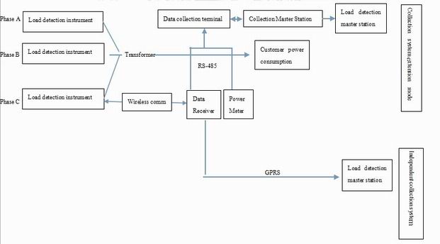
In order to solve these problems and help power distribution companies to detect the electricity-theft actions and crack down on the theft.Our company developed out a new “electricity theft monitoring system”. The system collect the first data by load detection device and compare it with the second data collected by user’s power meter.it can timely monitor the users’ electricity consumption value and avoid the theft.
The electric theft monitoring system is designed for monitoring the industrial and commercial consumption of electricity. The system is the outcome of our efforts for years in the power monitoring system.The system is quite effective and reliable,which is the good friend of power grid distribution enterprises
The Structure of the Anti-theft System(Especially for independent substation users)
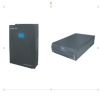
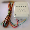
The electricity theft monitoring system is applied into anti-theft field and it’s special for the industrial and commercial power consumers.The system consists of Load detection instrument,wireless data receiver and Master station.
The Advantages of the Electric theft monitoring System
1.High reliability,hard to be damaged
2.Timely monitoring
3.High efficiency,solve the theft from the root.
4.Economical, the system’s cost is much lower than the amount of electricity that was stolen.
5.Easy and simple installation, can be installed even when there is electricity.
Purchase & Warranty
Purchase Procedure
Bueno Electric is an international company who can sell their products to every corner over the world.
1.If we have distributor in your country:
Please contact our local dealer for purchase issue.
2.If we don't have distributor in your country,please do the following steps:
1. Please read carefully our website and select the model number of Bueno Electric product that you are ready to order.To avoid any misunderstanding,please think of all details and take your special requirements into account.
2. Please send the following information to our sales team Email box:
A. Your full company information:Company name,Address,Country name,ZIP code,Telephone number.
B. Product information you would order: Product name,Model number,Quantity of each model.If you have special requests on product such as power supply voltage,connector type,temperature and so on,please add it to your PO.
3.Our sales team or system will make the Proforma Invoice for you automatically,which is the substitute of sales contract. Our sales team will send the invoice to you by Email or Fax.
4.After you receive the Proforma Invoice,please sign back and arrange the payment,once we receive your payment proof,we will organize the production and deliver the goods to your by air shipment or courier(Like DHL,FedEx,UPS,TNT and EMS) within the agreed lead time on the Invoice.
Note: If you only accpet other payment methods such as West Union and Paypal,please contact our sales team for negotiation.
Warranty Term
Bueno Electric products are warranted to be free from manufacturing defects in materials and workmanship starting from the shipping date. The warranty period of industrial communication products is 2 years.
Product warranties remain valid provided the product was properly installed and used. Defects, malfunctions, or failures of the warranted product caused by damage resulting from Force Majeure (such as floods, fire, etc.), environmental and atmospheric disturbances, other external forces such as power line disturbances, malfunction, plugging the board in under power, or incorrect cabling, and damage caused by misuse, abuse, and unauthorized alteration or repair, are not warranted. Customers are not allowed to open the case of the products without the authorization from Bueno Electric.
This warranty is limited to the repair and/or replacement, at Bueno Electric's sole discretion, of the defective product during its warranty period. Bueno Electric will replace any product found to be defective within the first three months from the shipping date of Bueno Electric said product was properly installed and used. For orders abroad, returning is inconvenient and unnecessary, so new products products will be shipped for replacement directly without the returning of old products.
After 90 days free replacement time, the product for replacement is not free, but the price of product for replacement shall be lower than market price if the time is within 2 years from shipping date, the exact price can be negotiated.
For large order projects, customers may purchase a post-warranty repair service. Such products may have a shorter chipset life cycle, or some parts may have a limited warranty from the original supplier of the parts. Please contact Bueno Electric's sales department if you would like to have this service.
Limitation of Liability:
The provisions of the warranty are in lieu of any other warranty, whether expressed or implied, written or oral. Bueno Electric's liability arising out of the manufacture, sale, or supplying of the product and its use, whether based on warranty, contract, negligence, product liability, or otherwise, shall not exceed the original cost of the product. In no event shall Bueno Electric be liable for unintended or consequential damages, including, but not limited to, a loss of profits or use damages arising out of the manufacture, sale, or supplying of the product.
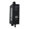
DeviceNet Repeater
DeviceNet Protocol Repeater
The DeviceNet Repeater is a kind of protocol bridge repeater,which is used to prolong the distance of DeviceNet communication,increase the nodes and improve the isolation ability.The repeater is based on industrial grade and it has low power consumption and easy mount way.When the DeviceNet repeater connects 2 DeviceNet networks,the 2 networks work at the same rate,the system has auto-sensing function.The DeviceNet repeater uses 5 PIN block terminal interface,which is in compliance with DeviceNet standard.
Technical Specification:
Bus Topology: Point to point link
Flow control function: Yes
DeviceNet Bus Interface: 5 PIN block terminal,in compliance with European standard
Transmission Type: Prototocl, DeviceNet frame transmission
Physical standard:DeviceNet,CAN2.0A、CAN2.0B
DeviceNet Baud Rate:125Kbps、250Kbps、500Kbps
500Kbps、800Kbps、1000Kbps;Auto-sensing
Buffering: 128 frames buffer
Power Input:DC9V-DC30V, < 2W ;
LED Status:Data,Power,Work status,Alarm
Dry Contact Alarm Output:Relay Interface,24V@1A,This email address is being protected from spambots. You need JavaScript enabled to view it.
Housing:D35mm DIN Rail,40x 110 x 74(mm)
Enclosure:Metal:IP40
Vibration:In compliance with IEC68-2-6
Weight:600g
Work Temperature:-25℃ ~ +75℃;Humidity:95% No condensing;
Storage:-45℃ ~ +85℃
Standard:CANOpen Standard
Electromagnetic:EN61000-4-2(8KV ESD)
EN61000-4-3,ENV50204(anti-electromagnetic 10V/m at 10KHz-1GHz)
EN61000-4-4(2KV Fast pulse group)
EN61000-4-5(Common mode 1KV,Differential mode 2KV SPD)
EN55022(Radiation class B)
CanOpen Repeater
CanOpen Protocol Repeater
The CANOpen Repeater is a kind of protocol bridge repeater,which is used to prolong the distance of CANOpen communication,increase the nodes and improve the isolation ability.The repeater is based on industrial grade and it has low power consumption and easy mount way.When the CANOpen repeater connects 2 CANOpen networks,the 2 networks work at the same rate,the system has auto-sensing function.The CANOpen repeater uses 5 PIN block terminal interface,which is in compliance with CANOpen standard.
Technical Specification:
Bus Topology: Point to point link
Flow control function: Yes
CANOpen Bus Interface: 5 PIN block terminal,in compliance with European standard
Transmission Type: Prototocl, CAN frame transmission
CAN standard:CAN2.0A、CAN2.0B
CANOpen Baud Rate:10Kbps、20Kbps、50Kbps、62.5Kbps、100Kbps、125Kbps、250Kbps、
500Kbps、800Kbps、1000Kbps;Auto-sensing
Buffering: 128 frames buffer
Power Input:DC9V-DC30V, < 2W ;
LED Status:Data,Power,Work status,Alarm
Dry Contact Alarm Output:Relay Interface,24V@1A,This email address is being protected from spambots. You need JavaScript enabled to view it.
Housing:D35mm DIN Rail,40x 110 x 74(mm)
Enclosure:Metal:IP40
Vibration:In compliance with IEC68-2-6
Weight:600g
Work Temperature:-25℃ ~ +75℃;Humidity:95% No condensing;
Storage:-45℃ ~ +85℃
Standard:CANOpen Standard
Electromagnetic:EN61000-4-2(8KV ESD)
EN61000-4-3,ENV50204(anti-electromagnetic 10V/m at 10KHz-1GHz)
EN61000-4-4(2KV Fast pulse group)
EN61000-4-5(Common mode 1KV,Differential mode 2KV SPD)
EN55022(Radiation class B)
Modbus Plus(MB+) Repeater
Modbus Plus(MB+) Protocol Repeater
The Modbus Plus Repeaters are designed to be used in Modbus Plus field bus cable segments,provide a link connection between two Modbus Plus segments. The Repeater contains two electrical interface for Modbus Plus.The electrical port of the Repeater has the same network connections, specifications and restrictions as other Modbus Plus devices, and must be treated accordingly.
The Modbus Plus bridge device is powered by 24V DC voltage. A redundant feed increases operational safety.
For the Modbus plus repeater using protocol repeater transmission technology, the modules can be connect MB+ cable segments ,You require a repeater in the following situations:
--When there are more than 32 stations (including repeaters) connected to the bus
--When electrically isolated bus segments are required or
--When the maximum cable length of a segment is exceeded
6 multicolored LED indicate the current operating status
Technical Data
Voltage/power supply
Operating voltage 12 V to 30 V DC, typ. 24 V,
Current consumption typ. 120 mA@24V
Signaling contact Max .switch DC24V@2A or This email address is being protected from spambots. You need JavaScript enabled to view it.
Signal transmission
Transmission rate Modbus Plus
Retimer (Electrical port)
Pulse Width Distortion/Jitter ±10ns
Cascade modules 3
Electrical port
Input/output signal Modbus Plus
Isolate voltage >= 1500VDC
PIN assignment Modbus Plus via 9–pin “D” connector
Electromagnetic compatibility (EMC)
Limit class B (EN 55022) EN 61000-4-2
EN 61000-4-3
Burst:
On power supply lines
shielded RS 485 bus lines
±2 kV (EN 61000-4-4)
Surge
Power lines,Shielded RS 485 lines
±1 kV symmetrical,±2 kV asymmetrical (EN 61000-4-5)
Others
Ambient temperature -25 °C to +75 °C
Storage temperature 40 °C to +85 °C
Relative humidity <95 %, non-condensing
Protection class IP 40
Dimensions (W x H x D) 62 x 132 x 120 mm
Weight approx. 600 g
ControlNet Repeater
ControlNet Protocol Repeater(Bridge)
The ControlNet Repeater are designed to be used in controlnet field bus cable segments,provide a link connection between two controlnet segments. The Repeater contains two electrical interface for controlnet .The electrical port of the Repeater has the same network connections, specifications and restrictions as other controlnet devices, and must be treated accordingly.
The ControlNet Repeater device is powered by 24V DC voltage. A redundant feed increases operational safety.
For The ControlNet Protocol Repeater using protocol repeater transmission technology, the modules can be connect controlnet cable segments ,You require a repeater in the following situations:
--When there are more than 32 stations (including repeaters) connected to the bus
--When electrically isolated bus segments are required or
--When the maximum cable length of a segment is exceeded
6 multicolored LED indicate the current operating status
Technical Data
Voltage/power supply
Operating voltage 12 V to 30 V DC, typ. 24 V,
Current consumption typ. 120 mA@24V
Signaling contact Max .switch DC24V@2A or This email address is being protected from spambots. You need JavaScript enabled to view it.
Signal transmission
Transmission rate CONTROLNET rate
Bit error rate < 10-9
Delay time valus 930ns/station
Retimer (Electrical port)
Input Signal distortion ±30 %
Bit length ±0.12 %
Output Mean bit length ±0.01 %
Cascade modules 3
Electrical port
Input/output signal CONTROLNET
Isolate voltage >= 1500VDC
PIN assignment BNC
Electromagnetic compatibility (EMC)
Limit class B (EN 55022) EN 61000-4-2
EN 61000-4-3
Burst:
On power supply lines
shielded RS 485 bus lines
±2 kV (EN 61000-4-4)
Surge
Power lines,Cable lines
±1 kV symmetrical,±2 kV asymmetrical (EN 61000-4-5)
Others
Ambient temperature -25 °C to +75 °C
Storage temperature 40 °C to +85 °C
Relative humidity <95 %, non-condensing
Protection class IP 40
Dimensions (W x H x D) 62 x 132 x 120 mm
Weight approx. 600 g
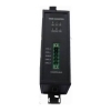
Profibus DP Repeater(Bridge Coupler))
Profibus DP to DP Coupler(Protocol Repeater)
Profibus DP repeater is a kind of protocol conversion repeater, which can provide BUS isolation.The module can be used independently, it can replace 6ES7972-0AA01-0xA0,it can prolong the transmission distance,increase the BUS nodes and bridge different networks.
Functions and Characters
- It does not require a configuration, the application is simple and convenient
- RS-485 interface,in compliance with EN50170 Part 1
- Support bus rates 9.6kBit/s, 19.2kBit/s ,45.45kBit/s, 93.75kBit/s, 187.5kBit/s, 500kBit/s;1.5MBit/s, 3MBit/s, 6MBit/s,12Mbit/s.Auto-sensing baud rates.
- Can be connected in a multi-drop BUS way,32 pieces can be connected together in a BUS line.
- Isolation:1.5KV
- Power is DC12 to 30V
- With failure alarm relay output
- 6 double color LED indication module current states
Technical Specifications:
Voltage/power supply
Operating voltage DC24V(20.4V….28.8V)
Reverse wiring ,Over voltage protection Yes
Signaling contact 0.1A @ 250V AC (350V DC),MOS
Power supply on PA Segment
Output voltage DC 31V(DC30V….32V)
Voltage monitoring 12V
Power failure bypass min. 5ms
Input current < 3A
Output current
Up to 50° ambient temperature < 500mA
Up to 60° ambient temperature < 360mA
DP electrical port
Setting transmission rate Automatic or Switch setting
Bus protocol PROFIBUS DP
Input/output signal RS 485 level
PIN assignment EN 50170 Part 1
Others
Storage temperature –40 °C to +85 °C
Relative humidity <95 %, non-condensing
Protection class IP 20
Dimensions (W x H x D) 40 x 110 x 74 mm
Housing material Die-cast zinc
Weight approx. 600 g