Sidebar
News Press

Administrator
CanOpen Multi-drop Bus Fiber Optic Converter

CAN-Open Multi-drop Bus Fiber Optic Converter
Descriptions:
The HFD-FO-OPE CAN Open Fiber Optic series products provide an optical point-to-point or bus network connection for CAN Open data interfaces on one or two, multimode or singlemode optical fibers. The CAN Open Point-to-Point Transmission units operate as the end or terminal points and provide an electrical connection and a two fibre optical connection. The units support CAN 1.0 and CAN 2.0 CAN standards, and Device Net. And are transparent to all high level protocols.
This series is available in either wall mount, DIN rail or 3U chassis card configurations.
Product Features of the CanOpen Fiber Optic Converter
Up to 1MB data rate
Multi mode and single mode
Single fiber solution
Wall mount, rack or chassis configurations
Product Features
Up to 1Mbps data rate
Multi mode and single mode
Single fiber solution,Dual power supplies
Other specs of the CANOpen BUS Fiber Optic Converter
|
Data |
|
|
Data Formats |
CAN1.0 ,CAN2.0 , ISO-11989 |
|
CAN Data Rate |
0 to 1Mbps |
|
Bit Error Rate |
<1 x 10-12 |
|
Connectors |
|
|
Data |
Screw Block Terminal |
|
Fiber |
ST, SC or FC (ST fitted as standard) |
|
Environmental |
|
|
Operating Temperat ure |
- 3 0 C--- +70 C |
|
Storage Temperature |
- 40 C--- +85 C |
|
Operating Humidity |
0- 95% |
|
MTBF |
>100,000 Hours |
|
Optical |
|
|
Fiber |
Multi mode or single mode |
|
Wavelength |
MM: 850nm, SM: 1310nm |
|
Number of fibers |
2 or 4 |
|
POWER |
|
|
Power Input |
AC 220V 110v or DC+110V +5V +12V +24V +48V Option |
|
Mechanical |
|
|
Dimensions |
43(W)×88.5(D)×124.5(H)mm DIN Rail |
Ordering Information:
|
Model Number |
Description |
Fiber No. |
Fiber Mode |
Fiber Connector |
|
HFD-FO-OPE-P1M |
Point to point Link,Single Fiber(BI-DI), 2km |
1 |
Multi Mode |
ST/SC/FC |
|
HFD-FO-OPE-P2M |
Point to point Link,Dual Fiber, 2km |
2 |
Multi Mode |
ST/SC/FC |
|
HFD-FO-OPE-P1S |
Point to point Link,Single Fiber(BI-DI), 20km |
1 |
Single Mode |
ST/SC/FC |
|
HFD-FO-OPE-P2S |
Point to point Link,Dual Fiber, 20km |
2 |
Single Mode |
ST/SC/FC |
|
HFD-FO-OPE-M2M |
Multi Point Bus Link,Dual Fiber(BI-DI), 2km |
2 |
Multi Mode |
ST/SC/FC |
|
HFD-FO-OPE-M4M |
Multi Point Bus Link,4 Fiber, 2km |
4 |
Multi Mode |
ST/SC/FC |
|
HFD-FO-OPE-M2S |
Multi Point Bus Link,Dual Fiber(BI-DI), 20km |
2 |
Single Mode |
ST/SC/FC |
|
HFD-FO-OPE-M4S |
Multi Point Bus Link,4 Fiber, 20km |
4 |
Single Mode |
ST/SC/FC |
DeviceNet Multi-drop Bus Fiber Optic Converter
DeviceNet Multi-drop Bus Fiber Optic Converter(New Model)
The HFD-FO-DEV series DeviceNet fiber optic products.which used the most advanced technlogy in the world,can provide an optical point-to-point or bus network connection for DeviceNet data interfaces on one or two, multi mode or single mode optical fibers. The DeviceNet Point-to-Point Transmission units operate as the end or terminal points and provide an electrical connection and a two fibre optical connection. The units support CAN 1.0 and CAN 2.0 CAN standards, and CAN. And are transparent to all high level protocols.
This series DeviceNet Fiber Optic Converter is available in either wall mount, DIN rail or 3U chassis card configurations.
Product Features of the Devicenet Bus fiber optic converter:
- Multimode and singlemode
- Single fiber solution supported
- New technology: Long distance transmission(20km) when baud rate is at 500K high speed, No cascading.
- DIN Rail, Wall mount, rack or chassis configurations, Dual power supply
Other specs of the Devicenet fiber optic converter:
| Data | |
| Data Formats | Device Net |
| CAN Data Rate | 125K/250K/500K |
| Bit Error Rate | <1 x 10-12 |
| Connectors | |
| Data | Screw Block Terminal |
| Fiber | ST, SC or FC (ST fitted as standard) |
| Environmental | |
| Operating Temperat ure | - 3 0 C--- +70 C |
| Storage Temperature | - 40 C--- +85 C |
| Operating Humidity | 0- 95% |
| MTBF | >100,000 Hours |
| Optical | |
| Fiber | Multi mode or single mode |
| Wavelength | MM: 850nm, SM: 1310nm |
| Number of fibers | 2 or 4 |
| POWER | |
| Power Input | AC 220V 110v or DC+110V +5V +12V +24V +48V Option |
| Mechanical | |
| Dimensions | DIN Rail 124.5*43*88.5mm(H*W*D) |
Odering Information:
|
Model Number |
Description |
Fiber No. |
Fiber Mode |
Fiber Connector |
|
HFD-FO-DEV-P1M |
Point to point Link,Single Fiber(BI-DI), 2km |
1 |
Multi Mode |
ST/SC/FC |
|
HFD-FO-DEV-P2M |
Point to point Link,Dual Fiber, 2km |
2 |
Multi Mode |
ST/SC/FC |
|
HFD-FO-DEV-P1S |
Point to point Link,Single Fiber(BI-DI), 20km |
1 |
Single Mode |
ST/SC/FC |
|
HFD-FO-DEV-P2S |
Point to point Link,Dual Fiber, 20km |
2 |
Single Mode |
ST/SC/FC |
|
HFD-FO-DEV-M2M |
Multi Drop Bus Link,Dual Fiber(BI-DI), 2km |
2 |
Multi Mode |
ST/SC/FC |
|
HFD-FO-DEV-M4M |
Multi Drop Bus Link,4 Fiber, 2km |
4 |
Multi Mode |
ST/SC/FC |
|
HFD-FO-DEV-M2S |
Multi Drop Bus Link,Dual Fiber(BI-DI), 20km |
2 |
Single Mode |
ST/SC/FC |
|
HFD-FO-DEV-M4S |
Multi Drop Bus Link,4 Fiber, 20km |
4 |
Single Mode |
ST/SC/FC |
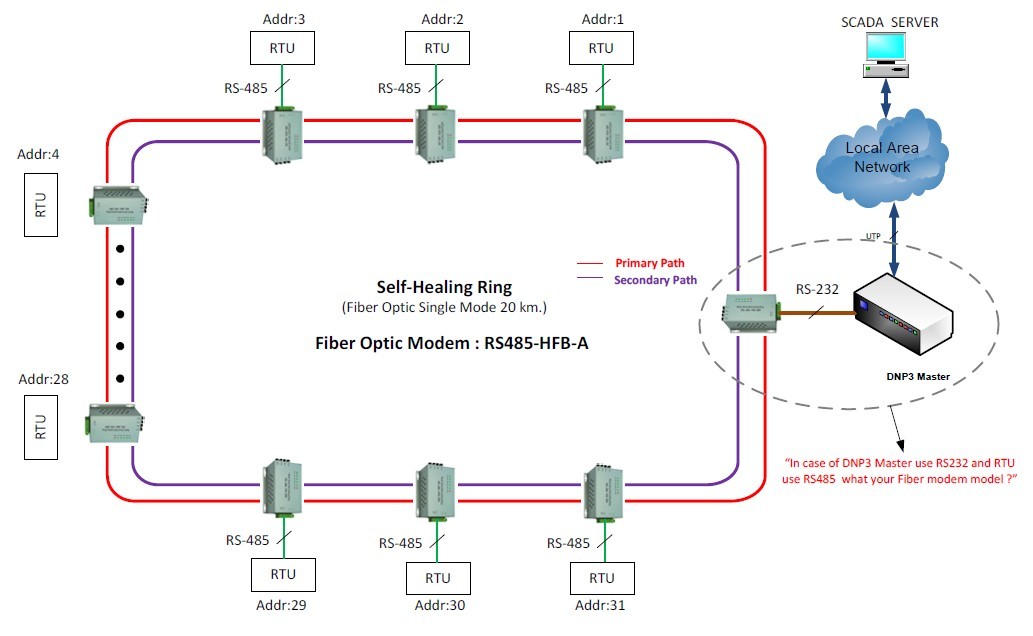
RS-485 Self-healing Ring Fiber Optic Converters Used in Qatar Chemical Factory

Self-healing Ring RS485 Fiber Optic Modem into UK Project
Over the past month of May,2012,we just signed a contract with Emersson for the order of 2200 units of industrial grade Rs485 fiber optic modems and our products will be used in their street light project.
Dry Contact Closure
Dry contact Closure:
Dry contact may mean any of the following in electronics:
No current: Dry contact can refer to a secondary set of contacts of a relay circuit which does not make or break the primary current being controlled by the relay. Usually some other contacts or devices have the job of starting or stopping the primary current being controlled. For example, a reed relay matrix switch is normally switched with all contacts dry. After the contacts are all connected, a wire spring relay is energized and connects a supervisory scan point, or main switch, through which the primary current being controlled then flows. Dry contacts are primarily employed in 49 volt or less (low voltage) distribution circuits. See also Contactor
No mercury: The wet contact of a Mercury-wetted relay gives certain operational advantages. Dry contacts means a relay that does not use mercury wetted contacts.
Dry joint: A dry contact can be confused with a dry joint, which is a type of poorly soldered joint in which the solder failed to wet the metal. These are liable to fail electrically. The term dry joint is also used less precisely to mean any sort of unsatisfactorily soldered joint.
Why CAN Bus Will Gradually Replace RS-485 and RS-232
CanBus is the earliest Bus technology is used in electronic systems, aircraft, tanks and other weapons of communications. Will this technology used in civil car originating in Europe, the bus network is used to the car in the car all kinds of sensor data transfer.
As the CANBUS developing and perfecting, as a kind of advanced technology, high reliability, good function and reasonable cost of remote network communication control mode, the CAN - BUS is no longer limited to automotive electronics field, also is widely applied to various other automation control system. In Europe, the americas, Asia CAN - bus bus technology has been widely applied in the field of engineering machinery, some famous international engineering machinery companies such as CAT, VOLVO, liebherr, widely used in the product CAN - bus bus technology, greatly improve the reliability of the whole machine, CAN be detected and maintainability, and at the same time improve the intelligent level. At home, the CAN - bus bus control system are also beginning to is widely used in auto control system, the construction machinery industry, such as automatic control, intelligent building, electric power systems, security monitoring, etc) are also being gradually popularized.
CANBUS technology application in our country started relatively late, the CIA in 1995 published a full version of CANopen communication protocol, gradually causes some units and the general application of science and technology workers of our country interest. Airlines big at the end of 1996, Beijing university published the CAN BUS principle and application of system design, a book, the application of the CAN BUS enthusiasm was up. Application after that, the CANBUS is like a bamboo shoots is published in the journal of science and technology of all kinds of related, at the same time, these applications like snowball, and so did the colleges and universities and scientific institutes, such as the development of positive enthusiasm and the electronics company of the chip, introduces the application of the CAN BUS technology more widespread inspired CAN - BUS technology research boom. Therefore, be regarded as the most promising fieldbus technology, by industry CAN BUS technology in our country, many in the industry has been widely used, its application level gradually improve. Because the CAN bus technology of good real-time, high reliability, the advantages of the good resistance to electromagnetic interference, make it quickly based on serial data work environment. Application in our country, the CAN - BUS technology is the key in body building monitoring and control system of elevator control system, the robot's distributed control system, ship control system and the medical instrument main monitoring system, testing system, mine monitoring system, and so on many domains, presents a thriving scene.
With China's industrial automation level unceasing enhancement, the CAN - BUS technology will inevitably with the advent of the era of fieldbus, and constantly in our country's economic reforms and the huge demand for open markets and more extensive application.In the fire alarm and other security fields,the control devices cancelled the some RS-485 and RS-232 interfaces and replace them with CAN Bus interfaces due to the high reliability of CAN Bus.In such a high automation world,people are more and more keen on high reliability Bus communications,Can Bus in near future will definitely be the main trend for industrial automation.
Bueno Synchronized Clock Application in British Power Plant
AMR and AMI
There’s plenty of room for confusion in today’s marketplace when it comes to defining advanced metering infrastructure (AMI)—the industry has yet to come to consensus on exactly what AMI means. Automated meter reading (AMR), on the other hand, is well defined and well represented.
As the industry leader in advanced metering technology, Itron provides its customers with a clear choice of both AMR and AMI technology. Itron’s AMR offering, ChoiceConnect™, provides proven performance and value along with the flexibility to migrate to more advanced capabilities as business needs change. OpenWay® by Itron is an entirely new generation of metering, communication and control technology designed to support a more expansive set of business and technology requirements for AMI.
To decide which technology is better suited to meet your business needs, it’s important to review the differences between AMR and AMI technology.
What is AMR?
Generally speaking, AMR refers to the ability to collect data from electricity, gas and/or water meters remotely and automatically via different communications networks. AMR is used primarily for monthly customer billing and reduced operational costs. AMR systems typically comprise meters fitted with communication modules, collection systems and supporting software to manage collection of the data. Some fixed network AMR systems, including ChoiceConnect, can also provide interval data collection and outage detection and restoration notification capabilities.
What is AMI?
Most often, AMI refers to systems that are capable of collecting detailed energy usage data frequently. Collection of more timely and granular data enables utilities to support time-based pricing and demand response programs, educate customers on energy consumption and alter usage patterns. AMI data is collected much more frequently, and the type of data collected is much more complex than in a typical AMR system. With AMI systems, this data is key to successful deployment and must be effectively managed.
AMR and AMI in the Marketplace
The business case and technology behind AMR are well-established in the marketplace. The cost savings, efficiency gains, customer service improvements and revenue cycle enhancements provided is the reason why many leading utilities of all types and sizes continue to deploy AMR technology in record numbers—according to the latest industry statistics, traditional AMR technologies still constitute the vast majority of new deployments.
OpenWay by Itron sets a new standard for AMI technology—both in form and function. Fundamentally, AMI represents an infrastructure that utilizes smart meters with advanced two-way communications for collection, querying and meter management. AMI systems empower utility customers to actively and frequently participate in demand response and energy conservation, while supporting movement toward the Smart Grid of the future.
Conclusion
Ultimately, business needs and regulatory conditions drive appropriate technology selection, and AMR technology continues to be a smart choice. Itron’s ERT®-based AMR technology provides the most cost-effective solution for automating collection of meter data for customer billing via drive-by AMR. Yet the system also enables utilities to deploy fixed network collectors over the same population of meters to enable more advanced capabilities such as interval data collection, positive outage and restoration notification. This combination of flexibility, reliability and cost optimization will continue to drive robust AMR system sales well in to the future.
As AMI technology matures, open standards are adopted, costs come down and the business case solidifies, AMI deployments will garner an increased share of the market. But for the foreseeable future, AMR and AMI technology are complementary offerings that will co-exist in the marketplace, with each utility’s unique combination of needs and objectives driving the selection of the most appropriate technology.
Substation Embedded Computer
Embedded Computer for Substation Communication
BUE-801 series embedded computer for substation communication can provides both industrial communication device and solution of the whole power and industrial automation system,which plays more important roles in industrial control and automation,especially in the substation automation.
1.Protocols it can support:
UCA2,TCP/IP, DNP3, OPC, Modbus RTU,RS-232,RS-485/422,Modbus TCP, IEC60870-5 series(IEC101,IEC102,IEC103,IEC104), IEC61850,NTP/SNTP,IRIG-B and other substation communication protocols.
2.Technical Specs:
Feature:
400Mhz Freescale MPC8308 CPU
128M DDR2 Memory
128M Nand Flash
2 Ethernet Ports
8 RS-232/485 Isolation Serial Ports
DIN-Rail Mount
|
System |
|
|
CPU |
Freescale MPC8308 PowerPC CPU,400MHz |
|
Memory |
DDR2 128M |
|
Flash |
8M Nor Flash |
|
128M Nand Flash |
|
|
Operating System |
Linux 2.6.29.6 |
|
LED |
|
|
|
System:Power x1,RUN x1, LAN:10/100/1000M x4(Link x2 Act x2) Serial:TxD x8,RxD x8 |
|
Others |
RTC,Buzzer,Watchdog Timer,Reset button,Console Port x1 |
|
Serial Communication |
|
|
Console Port |
Console Port RJ45 connector x1 RS232 115200bps N,8,1 |
|
Serial Port |
8 xRS-232/485 TB Interface connector software-selectable RS-232 Signals:TxD,RxD,GND RS-485 Signals:485A(Data+),485B(Data-) |
|
Protection |
Built-in 15KV ESD protection for all signals, 2KV iCoupler digital isolation protection |
|
Network Communication |
|
|
LAN |
Auto-sensing 10/100/1000Mbps x 2, RJ45 Build-in 1.5KV magnetic isolation protection |
|
Power Requirements |
|
|
Power Input |
Dual Power Input Design PWR1:9-48VDC or 9-48VAC PWR2:9-48VDC or 9-48VAC |
|
Lost power alarm |
Relay empty node |
|
Power Consumption |
|
|
|
8W@12VDC |
|
Mechanical |
|
|
Dimensions |
200(L)x121.01(W)x54.1(H) |
|
Installation |
DIN-Rail Mount |
|
Environmental |
|
|
Operating Temperature |
-20-60℃ |
|
Storage Temperature |
-30-80℃ |
|
Regulatory Approvals and Warranty |
|
|
EMC |
GB/T 17626.2-2006 Class 4 GB/T 17626.4-2008 Class 4 GB/T 17626.5-2008 Class 4 GB/T 17626.6-2008 Class 3 |
|
Warranty |
5 Years |